Downshift in hydrostatic drive work machine

a technology of hydrostatic drive and work machine, which is applied in the direction of fluid gearing, mechanical equipment, gearing, etc., can solve the problems of relatively rapid change of torque provided by the motor to the ground engaging wheels or tracks, affecting the efficiency and smoothness of various operations of the hystat drive system, and affecting the efficiency of the work machine. , to achieve the effect of increasing the pressure on the low clutch of the work machin

Inactive Publication Date: 2006-07-13
CATERPILLAR INC
View PDF5 Cites 11 Cited by
  • Summary
  • Abstract
  • Description
  • Claims
  • Application Information

AI Technical Summary

Benefits of technology

[0009] In one aspect, the present disclosure provides a method of downshifting in a hydrostatic drive work machine. The method includes the step of, if upon commanding a downshift in the work machine the work machine is not in a retarded mode, inducing a retarded mode in the same. The method further includes the steps of adjusting a displacement of each of a variable displacement pump and a variable displacement motor in a hydrostatic drive of the work machine, and increasing pressure on a low clutch of the work machine.
[0010] In another aspect, the present disclosure provides an article having a computer readable medium with a control algorithm recorded thereon. The control algorithm includes means for inducing a retarded mode in a work machine hydrostatic drive that includes a varia

Problems solved by technology

In many known designs, the efficiency and smoothness of various operations in the hystat drive system is limited by the physical capabilities of the work machine operator, as well as the limitations of the various system components.
In particular, slowing and accelerating the work machine can be relatively rough or inefficient if the operator is not well practiced in adjusting the pump and motor.
Where an operator unwittingly adjusts a pump or motor displacement too quickly, the relatively rapid change in torque provided by the motor to the ground engaging wheels or tracks can be problematic.
Excessively high torque, or changes in torque can induce in the work machine an excessively large acceleration or deceleration, or increase or decrease in the same, known in the art as “jerk.” Oper

Method used


Image

  • Downshift in hydrostatic drive work machine
  • Downshift in hydrostatic drive work machine
  • Downshift in hydrostatic drive work machine

Examples


Embodiment Construction

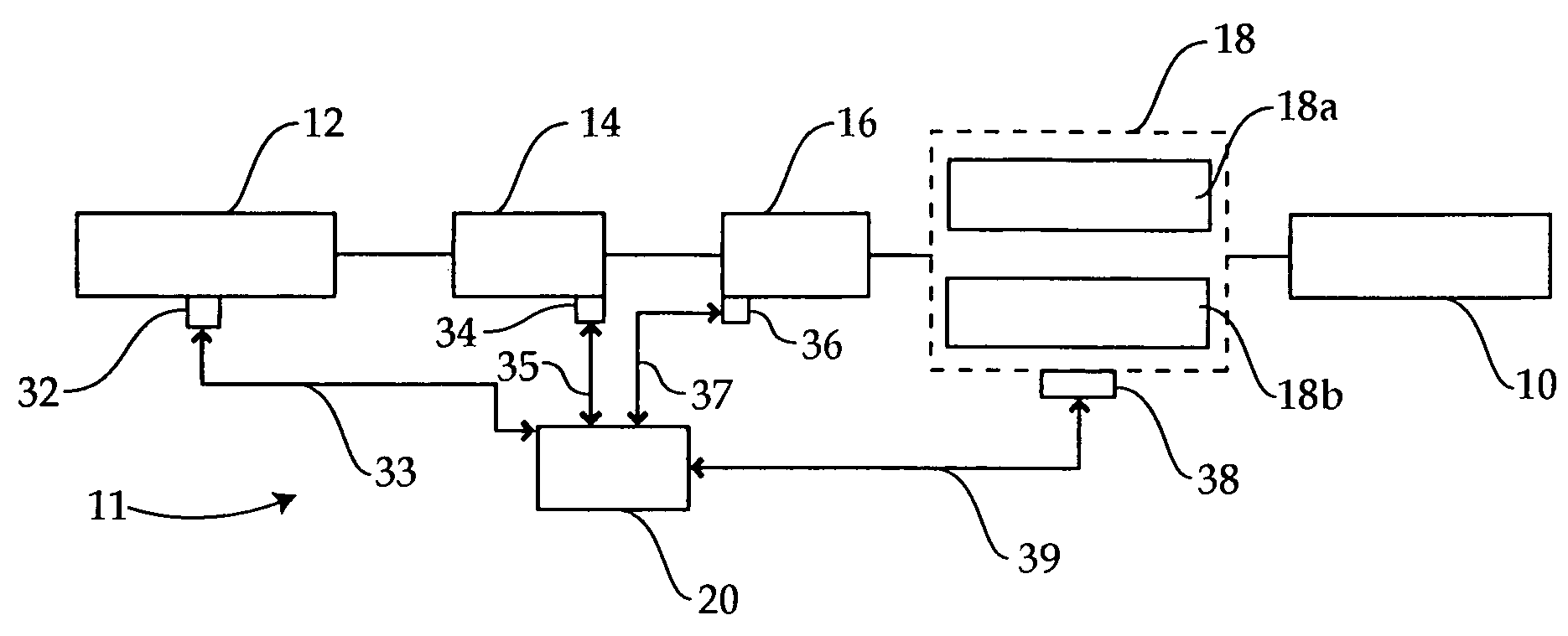
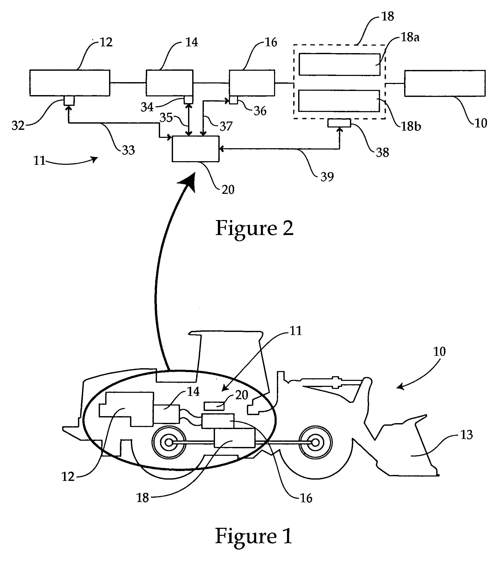
[0025] Referring to FIG. 1, there is shown a hydrostatic drive work machine 10. Work machine 10 includes a hydrostatic drive system 11 disposed therein, including an engine 12, a variable displacement pump 14, a variable displacement motor 16 and a transmission 18 having at least two gears, for example a low gear 18a and a high gear 18b. An electronic control module 20 is further provided, and is operable to electronically control the displacement of pump 14 and motor 16 and engagement of gears 18a or 18b, during downshifting in work machine 10, as described herein. Work machine 10 is illustrated as a front-end loader having a bucket 13; however, it should be appreciated that the design shown in FIG. 1 is exemplary only, and work machine 10 might be any of a wide variety of other hydrostatic drive work machines, many of which are known in the art.

[0026] Work machine 10 may be equipped with a set of controls which allow the operator to adjust an engine throttle and control travel di...


PUM


Abstract

The present disclosure provides a hydrostatic drive work machine, and a method and control module having a control algorithm for performing a downshifting event in the work machine. The method includes the step of inducing a retarded mode in the work machine, if upon commanding a downshift the work machine is not in a retarded mode. The method further includes the steps of adjusting a displacement of each of a variable displacement pump and a variable displacement motor in a hydrostatic drive of the work machine, and increasing pressure on a low clutch of the work machine. The control algorithm includes means for inducing a retarded mode in the work machine, if the work machine is not in a retarded mode upon commanding a downshift, with at least one of a variable displacement motor and a variable displacement pump in a hydrostatic drive of the work machine.

Description

TECHNICAL FIELD [0001] The present disclosure relates generally to hydrostatic drive work machines, and relates more particularly to a method and software control algorithm for downshifting in such a machine. BACKGROUND [0002] Hydrostatic or “hystat” drive refers generally to a drive train or a portion of a drive train in a work machine that utilizes hydraulic fluid pressurized by engine rotation as the motive force for propelling the work machine. In a typical design, a pump is driven with an output shaft of the engine and provides pressurized hydraulic fluid to a hydraulic motor, in turn coupled with one or more axles of the work machine. Commonly, both the pump and the motor have a variable displacement, allowing the relative torque and speed applied to a drive shaft of the work machine, and in turn to the wheels or tracks thereof to be varied. [0003] For example, where a work machine operator wishes to provide a relatively high torque to the work machine wheels or tracks, the di...

Claims


Application Information

Patent Timeline
IPC IPC(8): F16H47/00F16H61/40F16H61/4157
CPCB60T10/04F16H61/21Y10T477/636F16H61/4157Y10T74/19149F16H61/40
Inventor SHAH, VAIBHAV H.
Owner CATERPILLAR INC
Why Eureka
Try Eureka