Elevator brake

Inactive Publication Date: 2006-07-13
OTIS ELEVATOR CO
View PDF13 Cites 23 Cited by
  • Summary
  • Abstract
  • Description
  • Claims
  • Application Information

AI Technical Summary

Benefits of technology

[0009] According to another aspect, the subject invention relates to an elevator brake that includes a rotor having two concentric annular zones on one side thereof. Movable first and second brake plates are each independently acuatable into engagement with a different one of the zones. First and second springs bias the first and second brake plates, respectively, toward the one side of the rotor. Ind

Problems solved by technology

Thus, in addition to normal braking, the brake will automatically stop the car in the event of a power outage because the solenoid will lose power.
Although two separate brakes could be employed, doing so would add significant cost, complicate installation and reduce reliability.

Method used


Image

  • Elevator brake
  • Elevator brake

Examples


Embodiment Construction

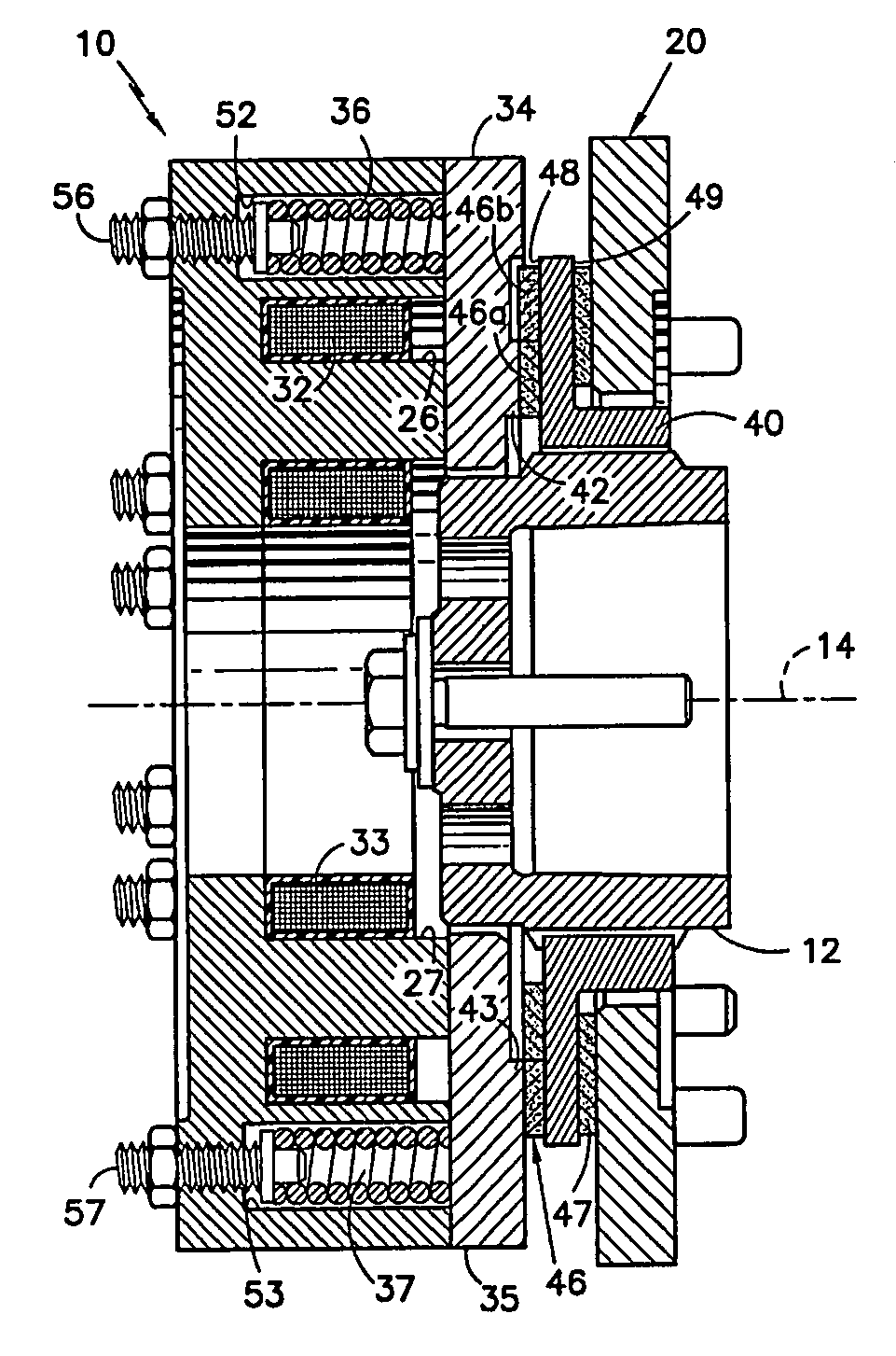
[0015]FIG. 1 shows an integrated disc brake assembly 10 according to a preferred embodiment of the subject invention. The assembly 10 comprises a housing 20, which may be secured to an outer wall of an elevator machine or gearbox housing (not shown). The assembly also includes electromagnets 32, 33, armature plates 34, 35, springs 36, 37, and a rotor 40.

[0016] The rotor 40 extends from a hub 12 that is mounted directly to a motor output shaft (not shown) of the elevator machine for rotation by the output shaft. For example, the end of the output shaft and the axis of the hub can have a bolt / socket arrangement (not shown) with complementary, axially extended, polygonal cross-sections that interlock so that the output shaft rotates the rotor 40, while the rotor 40 is permitted some small axial movement relative to the output shaft. Alternately, the hub 12 may be mounted in a similar manner to the drive sheave shaft (not shown) if the latter shaft is independent of the motor output sh...


PUM


Abstract

An elevator brake includes a rotor (40). Preferably, a front brake lining (46) is disposed on one side of the rotor and includes two concentric annular zones. Movable first and second brake plates (42,43) are each independently acuatable into engagement with a different one of the two concentric zones of the front brake lining.

Description

FIELD OF TIE INVENTION [0001] This invention relates to an improved elevator brake which is operable both to hold an elevator car at a landing during normal operation and to stop the car under emergency conditions such as power failure or overspeed. More particularly, this invention relates to a disk brake assembly that independently achieves both braking operations. BACKGROUND OF THE INVENTION [0002] Passenger elevators typically include an elevator car and a counterweight suspended by elevator ropes that run over a traction sheave. An electric motor drives the sheave to move the elevator ropes, thereby driving the car and counterweight up and down an elevator shaft (or hoistway) on guide rails. When the car is stopped at a desired landing, a brake holds the sheave or the motor's output shaft, thereby keeping the car in place. The brake typically is actuated by springs and is released by a solenoid. Thus, in addition to normal braking, the brake will automatically stop the car in t...

Claims


Application Information

Patent Timeline
IPC IPC(8): B66B5/16
CPCB66B5/02B66D5/14B66D5/30
Inventor SEVILLEJA-PEREZ, JOSEHORELANO-BLANCO, JOSE LUISSERVIA-RAYMUNDO, ARMANDO
Owner OTIS ELEVATOR CO
Why Eureka
Try Eureka