Power transmission device

a transmission device and power technology, applied in vessel construction, renewable energy generation, greenhouse gas reduction, etc., can solve the problems of reducing the overall efficiency, affecting reducing the efficiency of the power transmission system, so as to minimize the wind bearing size and maximize the blade siz

Inactive Publication Date: 2006-07-13
YU JIAHUA +5
View PDF5 Cites 28 Cited by
  • Summary
  • Abstract
  • Description
  • Claims
  • Application Information

AI Technical Summary

Benefits of technology

[0017] a blade rotating arrangement connected to respective spinning shaft for managing a rotational direction and speed so as to ensure the spinning shafts rotated reversed with respect to the revolution shaft at a speed ratio 1:2, such that when the revolution shaft is powered to rotate driving the power transmission frame into rotation, the blades will correspondingly rotated to maximize a wind bearing size of the blade in wind favorable condition and minimize the wind bearing size in wind undesirable condition.

Problems solved by technology

Unfortunately, when such device is disposed at a wind withstanding position, the resistance force of the blades would be correspondingly increased as well thus worsening the overall efficiency.
However, during the operation, the catch pin would withstand substantial force regardless of the wind condition.
The blades are free to shift within a wide range of space, thus making enormous noise in practices.
Such fixed wings design has been proven to have a smaller air withstanding area, and a weak lifting torque.
Currently, the hydrant generators unexceptionally employ turbine for converting hydrant power into electrical power, wherein the high speed water torrent is directed to impact onto the turbine.
Nevertheless, the turbine blade would withstand substantial bearing force under an against-current condition, thus wasting the power outputting efficiency.
On the other hand, current ship utilize the fuel driven mechanic to operate the propeller, which cause unnecessary energy consumption, and pollution.

Method used


Image

  • Power transmission device
  • Power transmission device
  • Power transmission device

Examples


Embodiment Construction

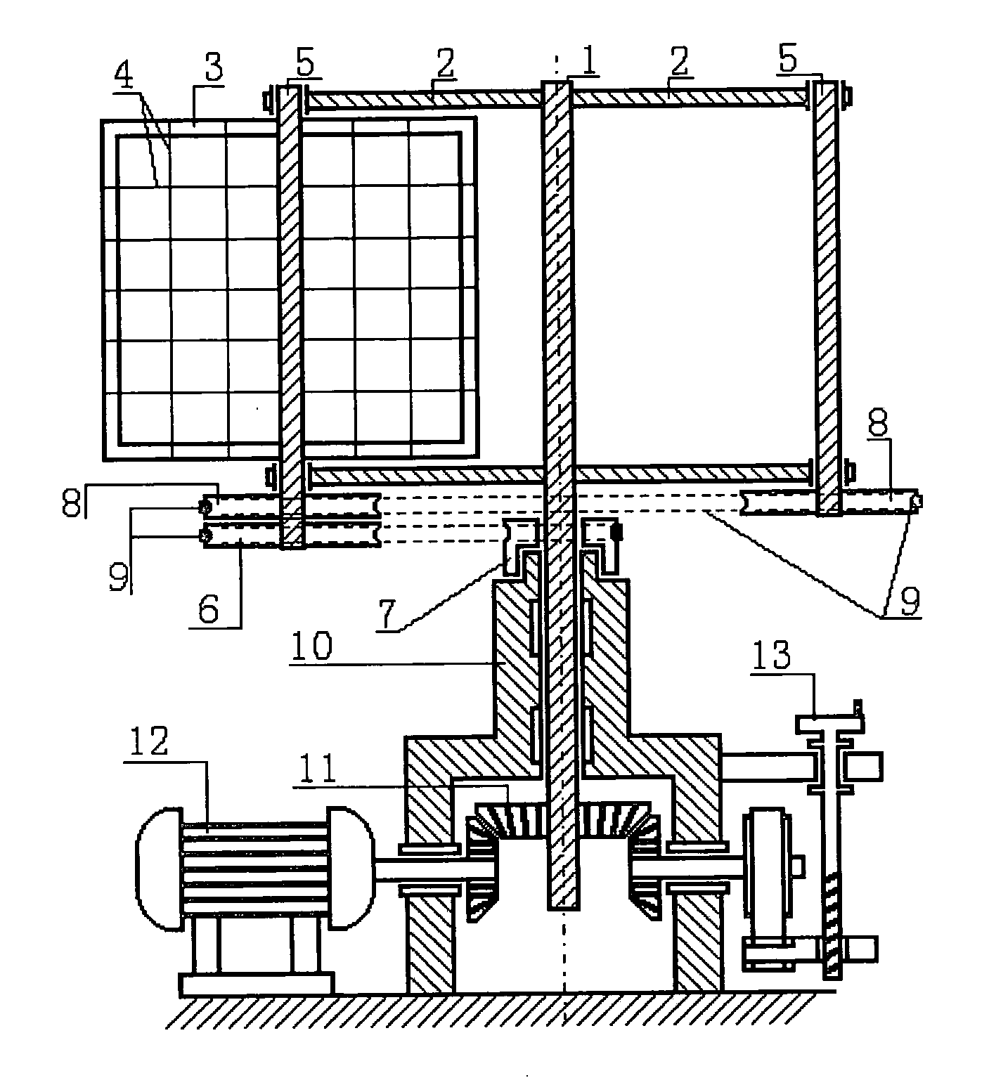
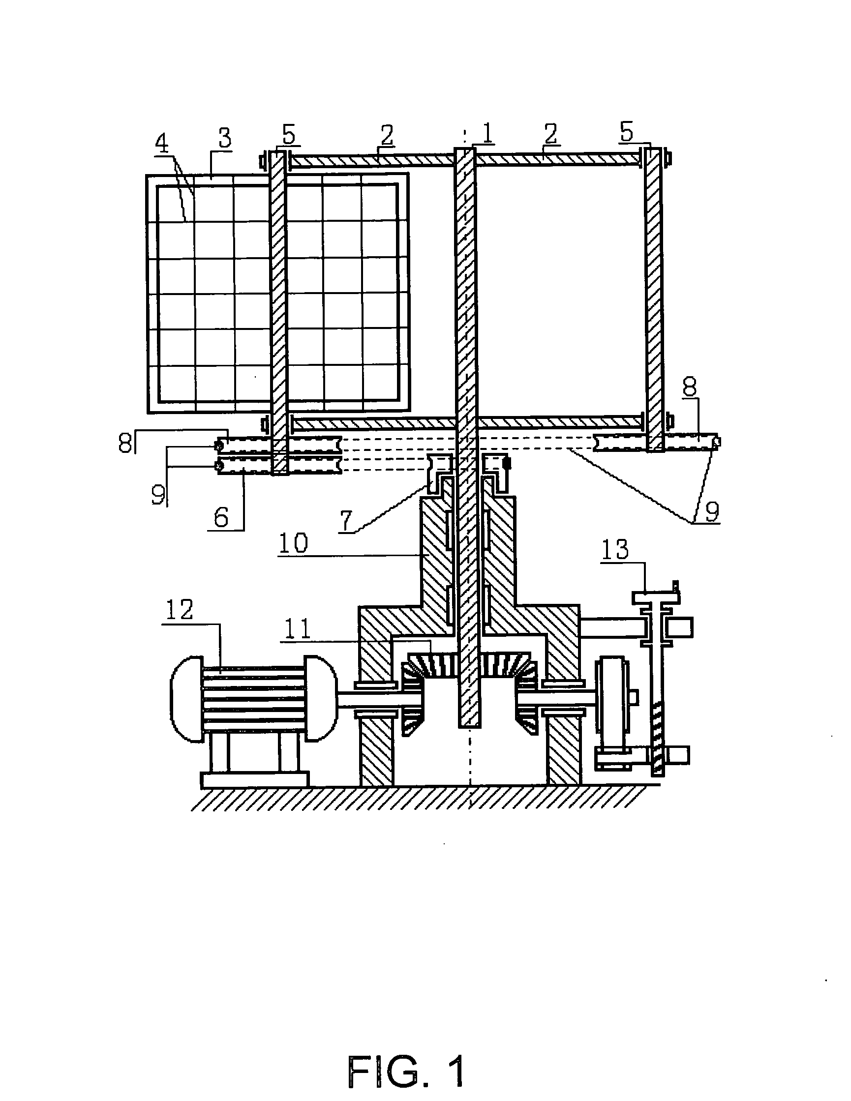
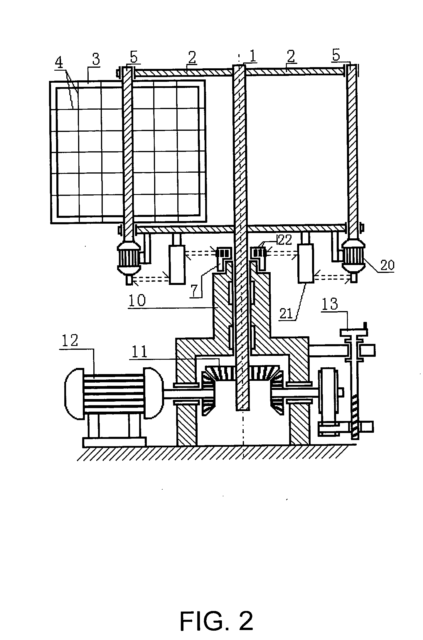
[0028] Referring to FIG. 1, a power transmission device according to a preferred embodiment of the present invention is illustrated. The power transmission device comprises a revolution shaft, a power transmission frame rotatably and coaxially coupled to the revolution shaft, comprising a plurality of spinning shaft symmetrically provided at outside edges of the power transmission frame; a plural blades rotatably and coaxially coupled to respective spinning shaft; and a blade rotating arrangement connected to respective spinning shaft for managing a rotational direction and speed, such that when the revolution shaft is power to rotate driving the power transmission frame to rotate, the spinning shaft provided at outer edges of the power transmission frame are capable of being rotated with a reversed direction, wherein the rotating speed ratio between the spinning shaft and the revolution shaft is 1:2.

[0029] In other words, the power transmission devices comprises a plurality of bla...


PUM


Abstract

The present invention discloses a power transmission device, including a revolution shaft, a power transmission frame wheel rotatably and coaxially coupled to the revolution shaft, a plurality of spinning shaft symmetrically provided at outside edges of the power transmission frame. A plural of blades rotatably and coaxially coupled to respective spinning shaft, and a blade rotating arrangement connected to respective spinning shaft for managing a rotational direction and speed of the blades, such that when the revolution shaft is powered to rotate driving the power transmission frame into rotation, the spinning shaft provided at outer edges of the power transmission frame are capable of being rotated with a reversed direction with speed ratio of 1:2 for maximizing the wind bearing size of the blade in wind favorable condition and decreasing the wind bearing size in wind undesirable condition.

Description

BACKGROUND OF THE PRESENT INVENTION [0001] 1 Field of Invention [0002] The present invention relates to power transmission devices applied for wind energy or hydraulic energy output and input, and more particularly, relates to power generator, flapping wing helicopter, hydrating generator, as well as vessels equipped with such kind of power transmission devices in varying applications. [0003] 2. Description of Related Arts [0004] The key point of the power transmission device which utilizes the blade to output or input the wind power or hydraulic power is to substantially enlarge the wind-bearing size or water-bearing size while the device is positioned at a wind favorable position, while substantially minimize the bearing area in upwind position. In conventional propeller-type power transmission device, the turbine blades are commonly prepared with spiral shaped with a predetermined curvature. This is due to the fact that such spiral shaped blade would withstand greater stress in s...

Claims


Application Information

Patent Timeline
Patent Type & Authority Applications(United States)
IPC IPC(8): B64C39/02B63H13/00B64C39/00B63H9/00B64C29/00
CPCB63H13/00B64C39/008F03D3/067F03D11/02F05B2210/16Y02E10/74Y02T70/58F03D15/00Y02E10/728Y02T70/5236F03D9/25F03D9/32F03D15/10F03D9/007
Inventor YU, JIAHUAYU, JIHE, MINJIECHEN, YULI, LINQIU, XIAOZHEN
Owner YU JIAHUA
Why Eureka
Try Eureka