Auxiliary power supply

Active Publication Date: 2006-07-13
ABB POWER GRIDS SWITZERLAND AG
View PDF7 Cites 21 Cited by
  • Summary
  • Abstract
  • Description
  • Claims
  • Application Information

AI Technical Summary

Benefits of technology

[0022] Driving mechanisms for switching equipment can be located at high poten

Problems solved by technology

A basic problem is then to provide insulation between the ground voltage potential and the high voltage potential of the high voltage installation.
The method requires a driving

Method used


Image

  • Auxiliary power supply
  • Auxiliary power supply
  • Auxiliary power supply

Examples


Embodiment Construction

[0028] The following description relates to the equipment and to the method.

[0029] Same reference numbers and labels are used in the various figures to signify parts that are of the same kind.

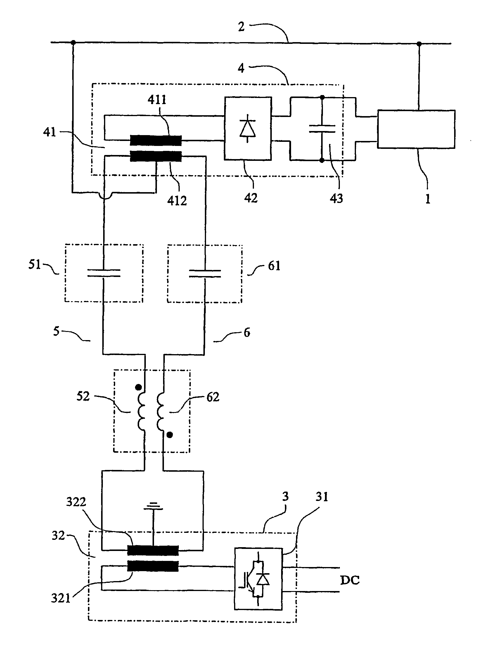
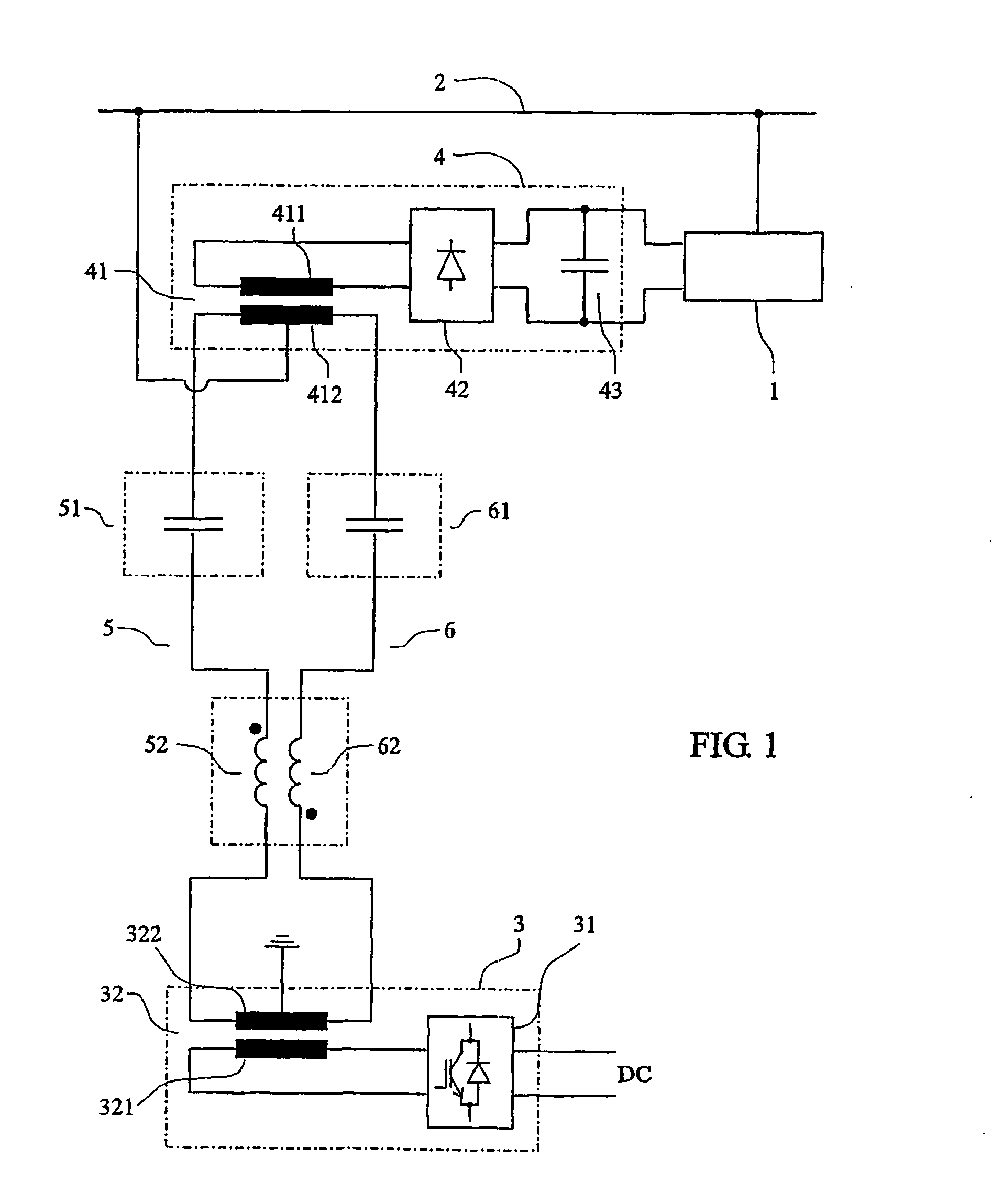
[0030]FIG. 1 shows a high voltage installation 1 in galvanic contact with a conductor 2. The installation may typically comprise switching elements such as circuit breakers or disconnectors, series capacitors, sensors for voltage and current, and / or monitoring and protective equipment.

[0031] A power source 3, located at ground level and at ground potential, comprises a high frequency voltage generator 31 in the form of a high frequency DC / AC-converter, and a ground level transformer 32.

[0032] The DC / AC-converter is supplied with a DC-voltage, in the figure designated with DC, and the output of the DC / AC-converter is supplied to a primary winding 321 of the ground level transformer. The ground level transformer has a secondary winding 322.

[0033] A load circuit 4, located at the high voltage...


PUM


Abstract

An auxiliary power supply equipment for a high voltage installation includes a power source at ground potential, a load circuit at high potential, and a transmission link for coupling the power source to the load circuit. The power source includes a high frequency voltage generator, and the transmission link comprises a first and a second current path. Each path is closed by capacitive coupling to provide insulation between the ground potential and the high potential, and each current path has a reactive compensation means for series compensation of reactive power generated by the capacitive coupling.

Description

TECHNICAL FIELD [0001] The present invention relates to a method for supplying auxiliary power to a high voltage installation, and to an auxiliary power supply equipment for a high voltage installation, having a power source at ground potential, a load circuit at high potential, and a transmission link for coupling the power source to the load circuit. [0002] High voltage is in this context considered to be a voltage in the range typically between 130 kV and 800 kV. [0003] Auxiliary power is in this context considered to be a power typically in the range of tens to hundreds of watts. [0004] High frequency is in this context considered to be a frequency that is at least two orders of magnitude higher than the system frequency of the high voltage installation, typically in the range of 10-100 kHz. BACKGROUND ART [0005] High voltage installations in high voltage power transmission systems comprise apparatus that are located dose to or in galvanic contact with the high voltage circuit. ...

Claims


Application Information

Patent Timeline
IPC IPC(8): G05F1/70H02J3/18H02J5/00H02J11/00H02M3/22
CPCH02J3/1807H02J11/00Y02E40/30H02M3/22H02J2001/002H02J1/002
Inventor ANGQUIST, LENNART
Owner ABB POWER GRIDS SWITZERLAND AG
Why Eureka
Try Eureka