
Disaster preventing system using digital radio communication

a technology of disaster prevention and digital radio communication, applied in frequency-division multiplex, fire alarms, instruments, etc., can solve problems such as insufficient operation, and achieve the effect of preventing the extent of damage caused by fir

Inactive Publication Date: 2006-07-13
YANG HAN GYU +1
View PDF6 Cites 18 Cited by
  • Summary
  • Abstract
  • Description
  • Claims
  • Application Information

AI Technical Summary

Benefits of technology

[0006] Therefore, the present invention has been made in view of the above problems, and it is an object of the present invention to provide a disaster prevention system using digital wireless communication capable of outputting a fire alarm when a fire occurs, displaying a location of the fire, and also driving an initial fire fighting device installed at the location of the fire so that the fire can be rapidly suppressed while still in its initial stage.
[0007] It is another object of the present invention to provide a disaster prevention system using wireless communication capable of providing convenience of construction and reducing construction costs.
[0008] It is a further object of the present invention to provide a disaster prevention system using wireless communication capable of stably operating even if external AC power is not supplied thereto.

Problems solved by technology

However, the earlier application has disclosed only that the prior art disaster prevention system is designed to automatically call telephones of government offices such as a fire station, police station, etc., and a manager when a fire occurs, but does not propose specific elements to achieve the object.
As such, since the prior art sprinkler is implemented to operate only if the temperature is over 80° C., it still has problems that it may not operate properly even if a fire occurs.

Method used


Image

  • Disaster preventing system using digital radio communication
  • Disaster preventing system using digital radio communication
  • Disaster preventing system using digital radio communication

Examples


Embodiment Construction

[0025] With reference to the attached drawings, the aspects mentioned above and other added aspects will be described in detail so that those skilled in the art can easily understand and reproduce the present invention based on preferred embodiments.

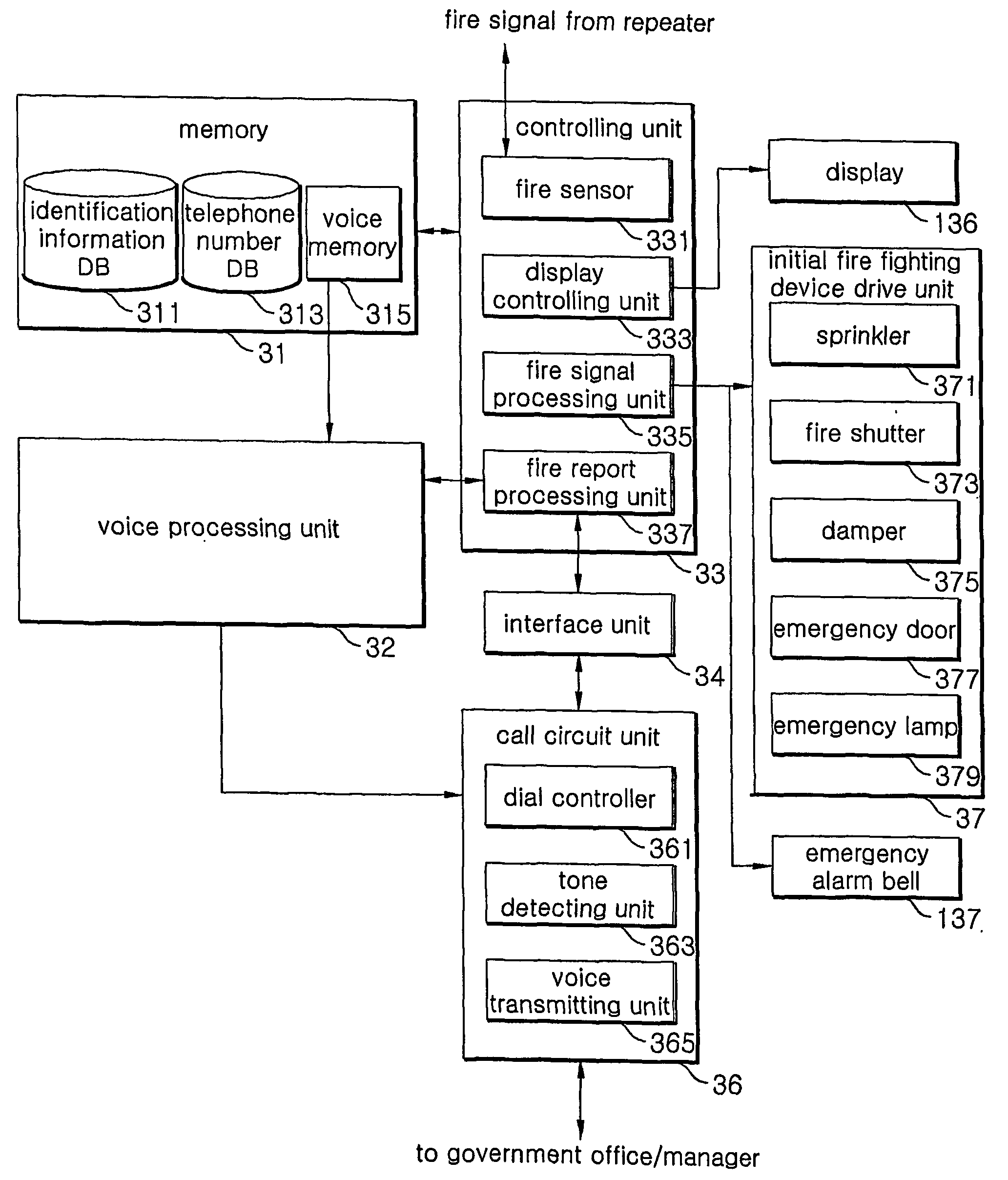
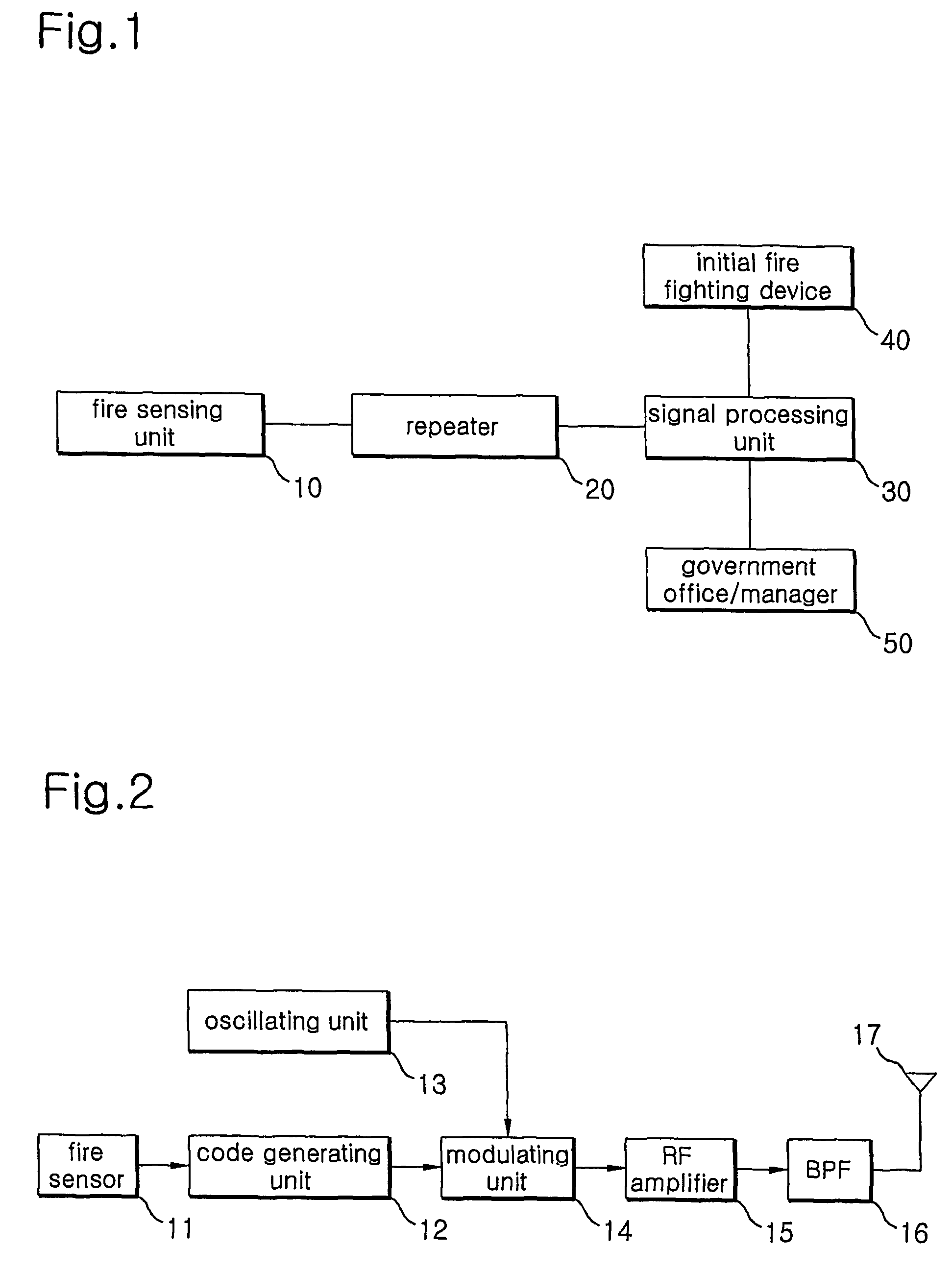
[0026]FIG. 1 is a schematic block diagram of a disaster prevention system according to the present invention. As shown in FIG. 1, the disaster prevention system according to the present invention comprises a plurality of fire sensing units 10, a plurality of repeater 20, a signal processing unit 30, an initial fire fighting device 40 and a government office / manager 50.

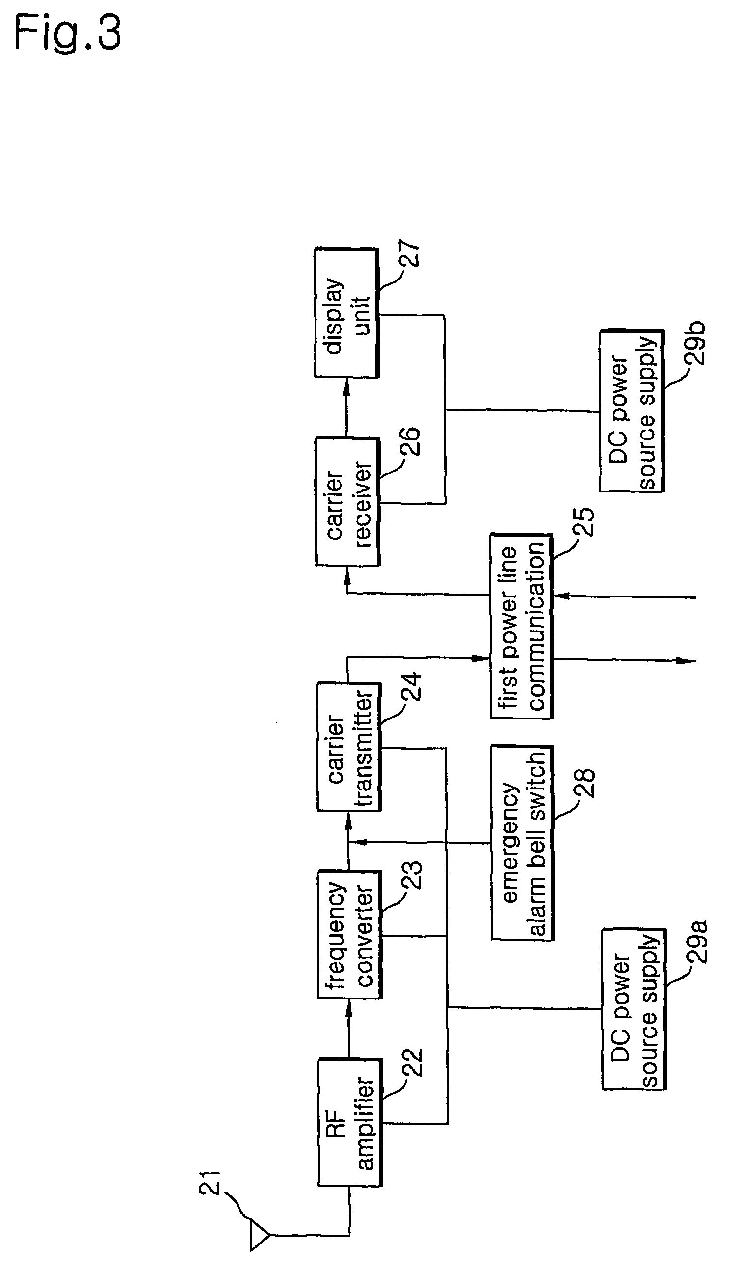
[0027] Each of the plurality of the fire sensing units 10 installed in a plurality of positions in a building senses a fire, and output fire information including fire sensor identification information and fire sensing information. Each repeater 20 installed in each floor of a building receives fire information outputted from the plurality of fire sensing units 10, displa...


PUM


Abstract

A disaster prevention system using a wireless digital communication is disclosed. The object of the present invention is capable of outputting a fire alarm when a fire occurs, displaying a location of the fire, and also driving an initial fire fighting device installed at the location of the fire so that the fire can be rapidly suppressed while still in its initial stage. It is another object of the present invention to provide a disaster prevention system using wireless communication capable of providing convenience of construction and reducing construction costs. It is a further object of the present invention to provide a disaster prevention system using wireless communication capable of stably operating even if an external AC power source is not supplied thereto. It is yet another object of the present invention to provide a disaster prevention system using wireless communication capable of automatically and rapidly calling corresponding office and corresponding office and corresponding manager when a fire occurs.

Description

[0001] transmitting the fire information wirelessly, at least one or more repeaters for receiving the fire information inputted from the fire sensing units, and a signal processing unit for analyzing the fire information inputted from the repeaters, displaying the location of the fire when a fire occurs, and outputting a fire alarm. [0002] The plurality of fire sensing units are installed in a plurality of positions in a building to sense fires. The repeaters are installed in each floor of the building to receive fire information inputted from the plurality of fire sensing units. A signal processing unit is installed in a main management suite to control and manage the entire building, for example, a guardroom to monitor a fire occurrence while it transmit / receives fire information in real-time to / from the repeater. If a fire occurs, the repeater and the signal processing unit display the location of the_fire, respectively, and output a fire alarm, so that occupants of the building ...

Claims


Application Information

Patent Timeline
Patent Type & Authority Applications(United States)
IPC IPC(8): G08B25/00A62C37/36H04M11/04A62C37/10G08B1/08G08B17/00A62C99/00G08B7/06G08B25/06G08B25/08
CPCA62C99/009G08B7/06G08B17/00G08B25/005G08B25/009G08B25/06H04M11/04
Inventor YANG, HAN-GYUKIM, JANG-SEOP
Owner YANG HAN GYU
Learn More