Method and apparatus for reducing electromagnetic emissions from electronic circuits

a technology of electronic circuits and electromagnetic emissions, applied in the field of shielding electromagnetic emissions generated by electronic circuits, can solve the problems of high-speed electronic circuits (such as microprocessors or digital signal processors) generating high levels of electromagnetic emissions, proximate electronic circuits to malfunction, interference with other electronic circuit operations, etc., to reduce electromagnetic emissions, reduce the space required for the electromagnetic emission shield, and reduce the effect of electromagnetic emissions

Inactive Publication Date: 2006-07-13
RICHEY MANUEL +1
View PDF15 Cites 58 Cited by
  • Summary
  • Abstract
  • Description
  • Claims
  • Application Information

AI Technical Summary

Benefits of technology

[0004] The present invention is directed to an electronic circuit that includes at least one electrical component and at least one grounding point, as well as a first layer of non-conductive coating and a second layer of conductive coating. The non-conductive coating is applied over the electrical component in such a manner that the non-conductive coating does not coat the grounding point. Preferably, the non-conductive coating conforms to the underlying electrical component so as to protect the electrical component from environmental conditions, such as exposure to water or humidity. The conductive coating is then applied over the non-conductive coating (and the underlying electrical component) and the grounding point so as to ground the conductive coating. The conductive coating thus acts as a shield for the electrical component to thereby reduce electromagnetic emissions from the electronic circuit. Preferably, the conductive coating conforms to the non-conductive coating (and the underlying electrical component) and the grounding point so as to minimize the space required for the electromagnetic emissions shield.
[0005] In a first exemplary embodiment, the coated electronic circuit includes a plurality of electrical components and a plurality of ground pa

Problems solved by technology

Electronic circuits often generate electromagnetic fields that can interfere with the operation of other electronic circuits.
In particular, high-speed electronic circuits (such as microprocessors or digital signal processors) tend to generate high levels of electromagnetic emissions.
The result is electromagnetic interference (EMI) that can interfere with the operation of the proximate electronic circuits, or even cause the proximate electronic circuits to malfunction.
Radio receivers, which are intentionally designed to be sensitive to electromagnetic s

Method used


Image

  • Method and apparatus for reducing electromagnetic emissions from electronic circuits
  • Method and apparatus for reducing electromagnetic emissions from electronic circuits
  • Method and apparatus for reducing electromagnetic emissions from electronic circuits

Examples


Embodiment Construction

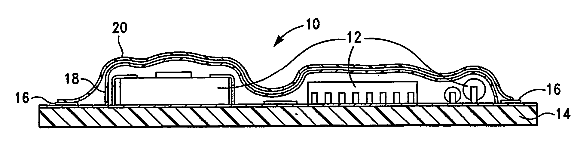
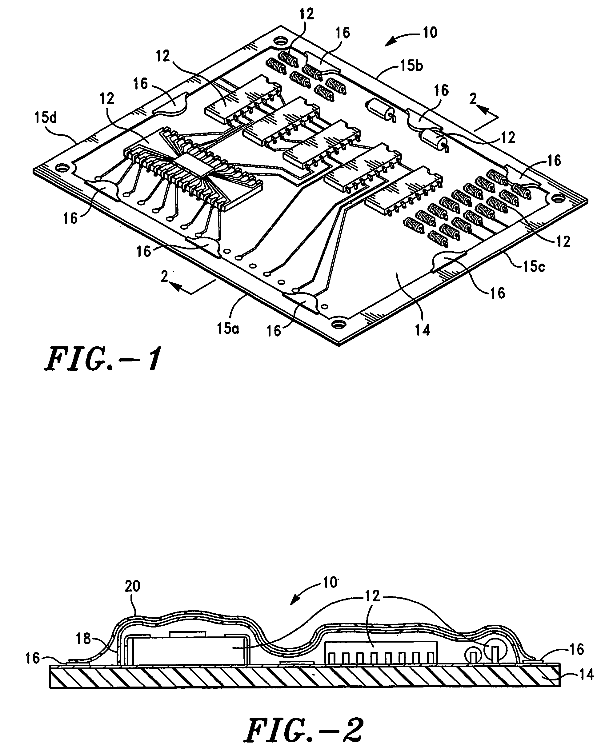
[0011] A typical electronic circuit is depicted in FIG. 1, and coated electronic circuits in accordance with exemplary embodiments of the present invention are depicted in FIGS. 2-4. While the invention will be described in detail hereinbelow with reference to these exemplary embodiments, it should be understood that the invention is not limited to the specific configurations of the electronic circuits shown in these embodiments. Rather, one skilled in the art will appreciate that a wide variety of configurations of electronic circuits may be implemented in accordance with the present invention.

[0012] Referring to FIG.1, a typical electronic circuit 10 is shown that includes a plurality of individual electrical components or circuits 12 mounted on a printed circuit board 14. It should be understood that the invention is not limited to any particular number or types of electrical components. Rather, the invention may be applied to any electronic circuit in which it is desired to red...


PUM


Abstract

An electronic circuit (10) comprising at least one electrical component (12) and at least one grounding point (16) is provided that includes a first layer of non-conductive coating (18) and a second layer of conductive coating (20). The non-conductive coating (18) is applied over the electrical component (12) in such a manner that the grounding point (16) remains uncoated. The conductive coating (20) is applied over the non-conductive coating (18) and the grounding point (16) so as to ground the conductive coating (20). The conductive coating (20) thus shields the electrical component (12) to thereby reduce electromagnetic emissions from the electronic circuit (10). Various exemplary embodiments of the coated electronic circuit and associated method are provided.

Description

FIELD OF THE INVENTION [0001] The present invention relates generally to electronic circuits, and more particularly to shielding electromagnetic emissions generated by electronic circuits. DESCRIPTION OF RELATED ART [0002] Electronic circuits often generate electromagnetic fields that can interfere with the operation of other electronic circuits. In particular, high-speed electronic circuits (such as microprocessors or digital signal processors) tend to generate high levels of electromagnetic emissions. Sensitive electronic circuits located in close proximity to the high-speed electronic circuits can detect the electromagnetic emissions generated thereby. The result is electromagnetic interference (EMI) that can interfere with the operation of the proximate electronic circuits, or even cause the proximate electronic circuits to malfunction. Radio receivers, which are intentionally designed to be sensitive to electromagnetic signals, are especially susceptible to EMI. [0003] In an ef...

Claims


Application Information

Patent Timeline
IPC IPC(8): H05K9/00H05K1/02H05K3/28
CPCH05K1/0218H05K3/284H05K9/0024H05K9/0039H05K9/0043
Inventor RICHEY, MANUELREIM, KENNETH TERRY
Owner RICHEY MANUEL
Why Eureka
Try Eureka