
Systems and methods providing high availability for distributed systems

a distributed system and high availability technology, applied in the field of distributed system environments, can solve the problems of inability to obtain information from the service host regarding the particular application session, inability to provide continuity of applications, and inability to provide application processing information, etc., to achieve the effect of high availability and facilitate recovery

Inactive Publication Date: 2006-07-13
UBIQUITY SOFTWARE CORP
View PDF10 Cites 60 Cited by
  • Summary
  • Abstract
  • Description
  • Claims
  • Application Information

AI Technical Summary

Benefits of technology

[0005] The foregoing distributed system architecture may comprise one or more equipment clusters of a plurality of processor-based systems, e.g., open architecture processor-based systems such as general purpose processor-based systems. The processor-based systems of an equipment cluster preferably cooperate to host one or more application servers. Redundancy is provided with respect to equipment of the equipment clusters, according to embodiments of the present invention, to provide high availability with respect to equipment used in providing services of the application servers as well as to provide continuity of applications provided by the application servers.
[0006] Various equipment elements of an equipment cluster may be provided different levels and / or types of redundancy according to the present invention. For example, according to an embodiment of the invention equipment elements providing execution of an application server (referred to herein as a “service host”) are provided 1:N redundancy, such as through the use of a pool of equipment available to replace any of a plurality of service hosts. When a service host is determined to have failed, an equipment element from the pool of equipment may be assigned to replace the failed service host, and the failed service host may be restarted and added back to the pool of equipment or taken offline. The use of such a pool of equipment elements facilitates recovery from multiple subsequent failures according to embodiments of the invention.
[0012] Embodiments of the present invention may implement 1:1 redundancy in the alternative to or in addition to the aforementioned 1:N service director redundancy. For example, 1:1 redundancy in combination with 1:N redundancy, such as discussed above with reference to service hosts, may be implemented with respect to service directors. However, service directors of embodiments of the present invention need not share substantial information in order to enable application continuity. Accordingly, 1:1 redundancy may be foregone in favor of 1:N redundancy in such embodiments without incurring substantial communication overhead, unacceptable delays in application processing, or application discontinuity.
[0016] The foregoing embodiments provide robust and reliable high availability equipment implementations, insuring no single point of failure of any critical traffic bearing element. Moreover, embodiments of the invention provide for continuity of applications in the event of equipment failure.

Problems solved by technology

Although the foregoing 1:N redundancy may be relied upon to provide high availability with respect to service hosts of an equipment cluster, such redundancy may not provide continuity of applications.
Specifically, if a service host fails, it may be impossible to obtain information from that service host regarding the particular application sessions then being conducted by the service host.
Moreover, even if such information may be obtained from the failed service host, transferring such information to equipment from the pool of equipment may require appreciable time, and thus result in unacceptable delays in application processing.
Accordingly, although a service host may be quickly replaced from an equipment pool, thereby providing high availability, application processing in process may be disrupted or unacceptably delayed, thereby preventing application continuity.

Method used


Image

  • Systems and methods providing high availability for distributed systems
  • Systems and methods providing high availability for distributed systems
  • Systems and methods providing high availability for distributed systems

Examples


Embodiment Construction

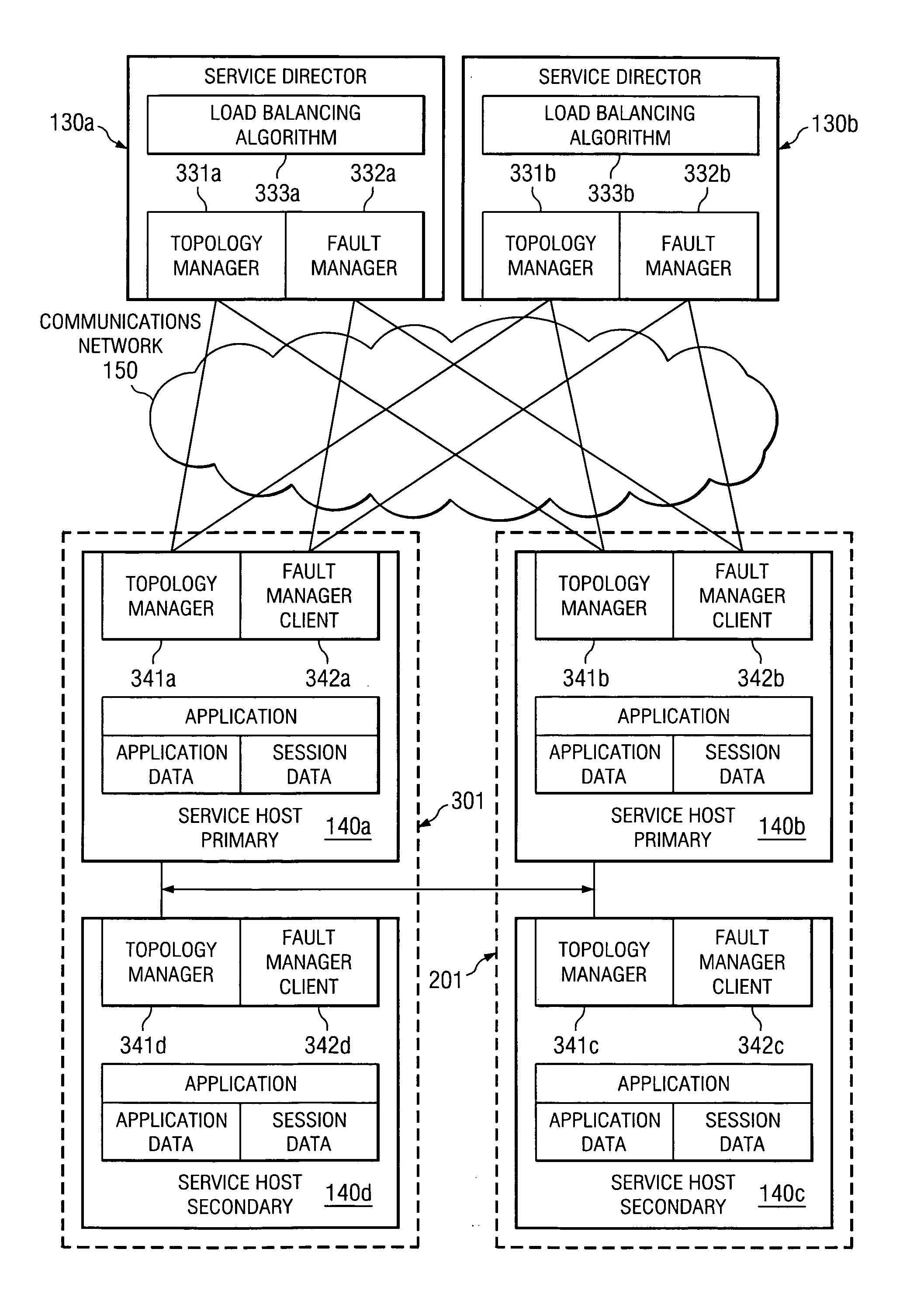
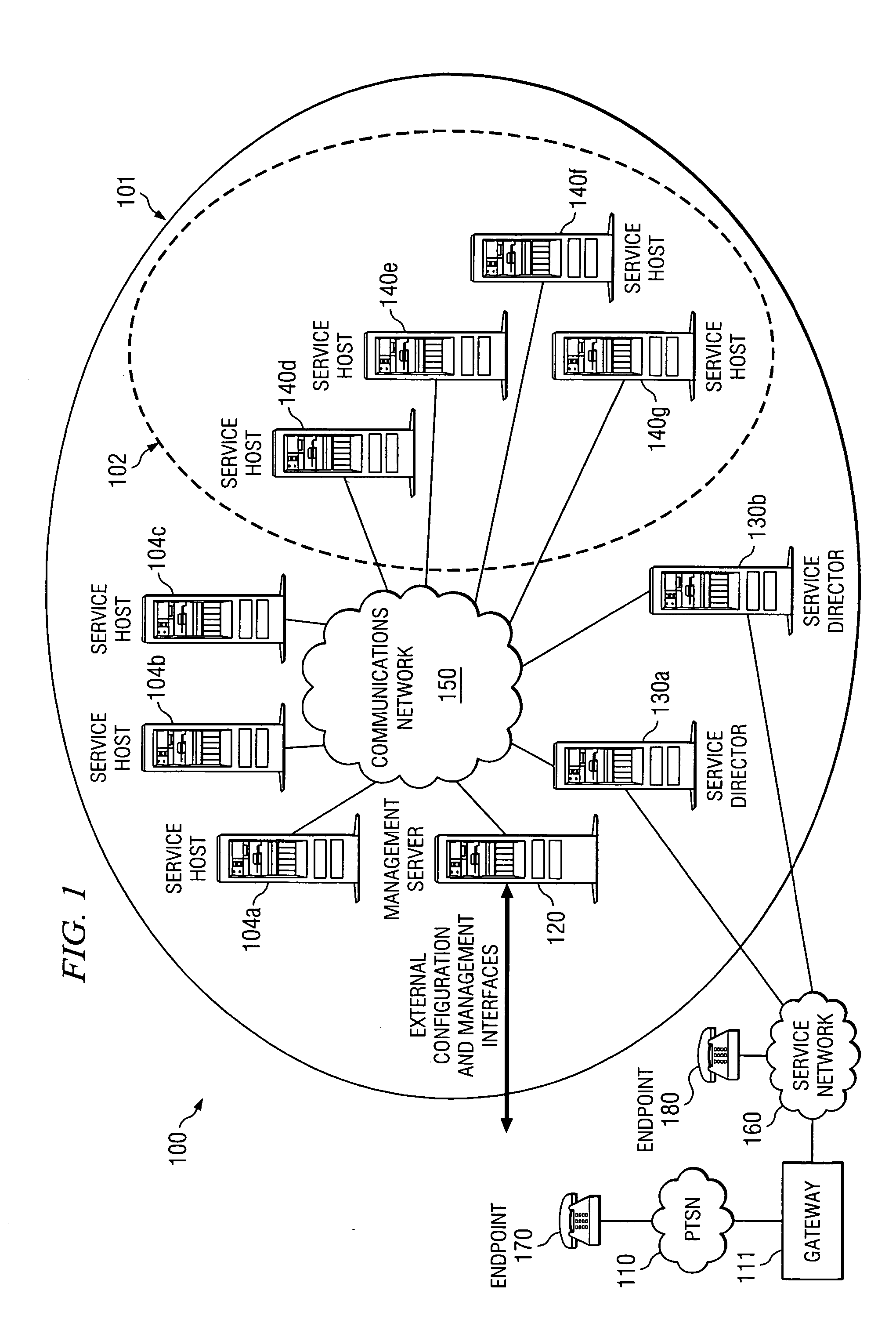
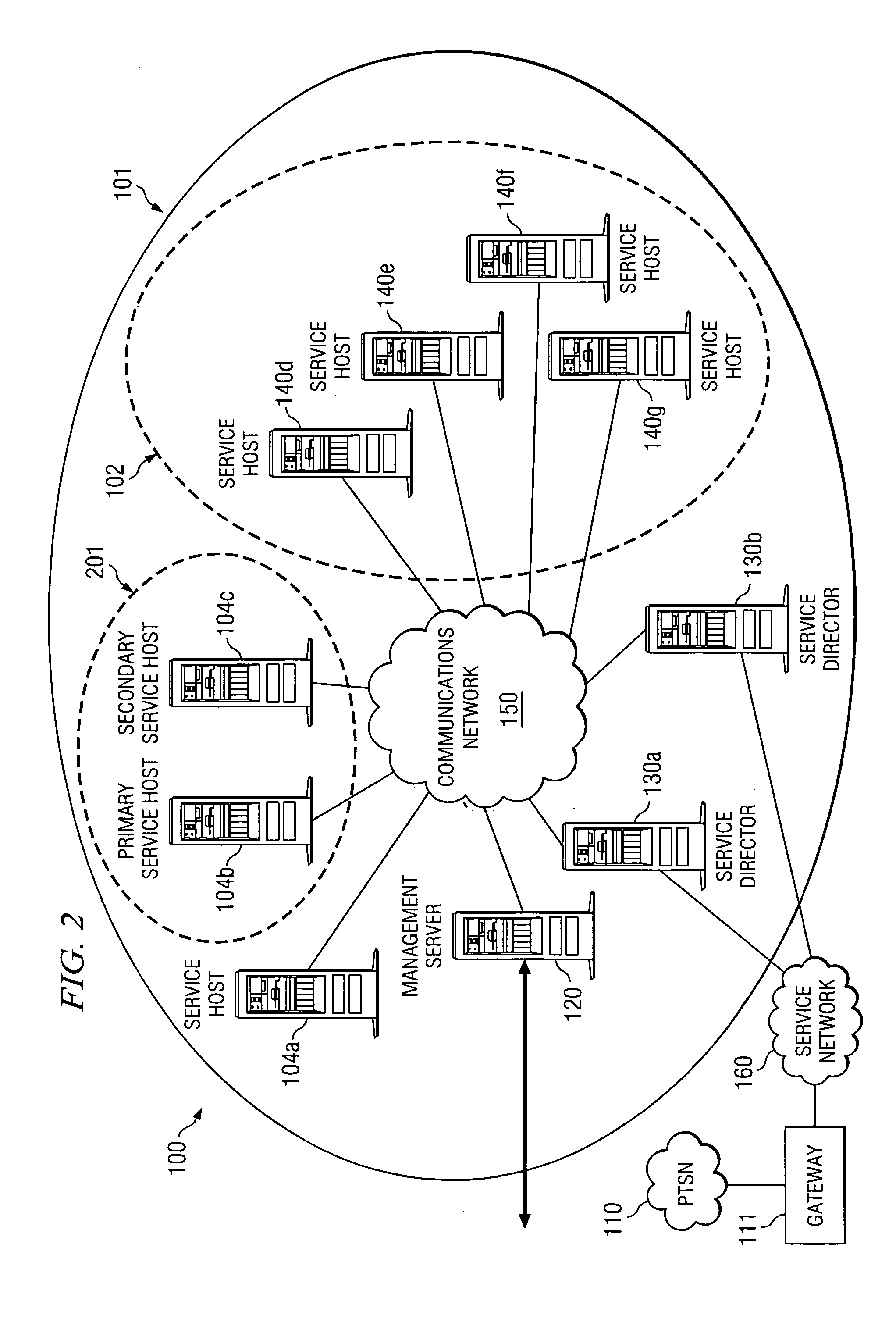
[0024] Directing attention to FIG. 1, distributed system architecture 100 is shown being provided high availability with respect to equipment deployed therein according to an embodiment of the present invention. Distributed system architecture 100 of the illustrated embodiment includes a plurality of equipment elements, shown here including management server 120, service directors 130a and 130b, and service hosts 140a-140g, associated with equipment cluster 101. It should be appreciated that the particular numbers of equipment elements and types illustrated in FIG. 1 are merely exemplary, and thus embodiments of the invention may comprise various numbers and configurations of equipment elements. Similarly, although only a single equipment cluster is shown in distributed system architecture 100 for simplicity, it should be appreciated that any number of equipment clusters, as may comprise various numbers and configurations of equipment elements and as may share one or more equipment ...


PUM


Abstract

Disclosed are systems and methods which provide high availability with respect to equipment deployed in a distributed system architecture. The distributed system architecture may comprise one or more equipment clusters of a plurality of processor-based systems cooperating to host one or more application servers. Redundancy is provided with respect to equipment of the equipment clusters to provide high availability with respect to equipment used in providing services of the application servers as well as to provide continuity of applications provided by the application servers. Various equipment elements of an equipment cluster may be provided different levels and / or types of redundancy. Other equipment elements of an equipment cluster may be provided different levels and / or types of redundancy. Equipment elements may operate to assign sessions to particular equipment elements for load balancing

Description

TECHNICAL FIELD [0001] The present invention relates generally to distributed system environments and, more particularly, to providing high availability for distributed systems. BACKGROUND OF THE INVENTION [0002] Equipment providing services with respect to various environments is often expected to provide high availability. For example, equipment utilized with respect to carrier based telecommunications environments is generally required to meet 99.999% (often referred to as “five nines”) availability. In providing high availability implementations, all critical elements within a deployment need to be redundant, with no single point of failure, and providing continuous service during an equipment failure without service being appreciably affected (e.g., all services seamlessly continued without appreciable delay or reduction in quality of service). The foregoing level of availability has traditionally been implemented in telecommunications environments by closely coupling the syste...

Claims


Application Information

Patent Timeline
IPC IPC(8): G06F11/00H04J3/14H04L69/40
CPCG06F11/2038G06F11/2041G06F11/2048H04L1/22H04L67/1008H04L67/1002H04L69/40H04L67/1001
Inventor DALLY, JOHNDOYLE, MICHAELHAYWARD, STEVELIDDELL, GETHINSTEADMAN, JAMES
Owner UBIQUITY SOFTWARE CORP
Features
  • Generate Ideas
  • Intellectual Property
  • Life Sciences
  • Materials
  • Tech Scout
  • Unparalleled Data Quality
  • Higher Quality Content
  • 60% Fewer Hallucinations
Learn More