
Architecture for control systems

a control system and architecture technology, applied in the field of control systems, can solve the problems of limited functionality provided to the control system by the devices, limited to single types, and inability to transfer and load programs into products from different vendors

Inactive Publication Date: 2006-07-13
PIERONEK DONALD
View PDF17 Cites 44 Cited by
  • Summary
  • Abstract
  • Description
  • Claims
  • Application Information

AI Technical Summary

Benefits of technology

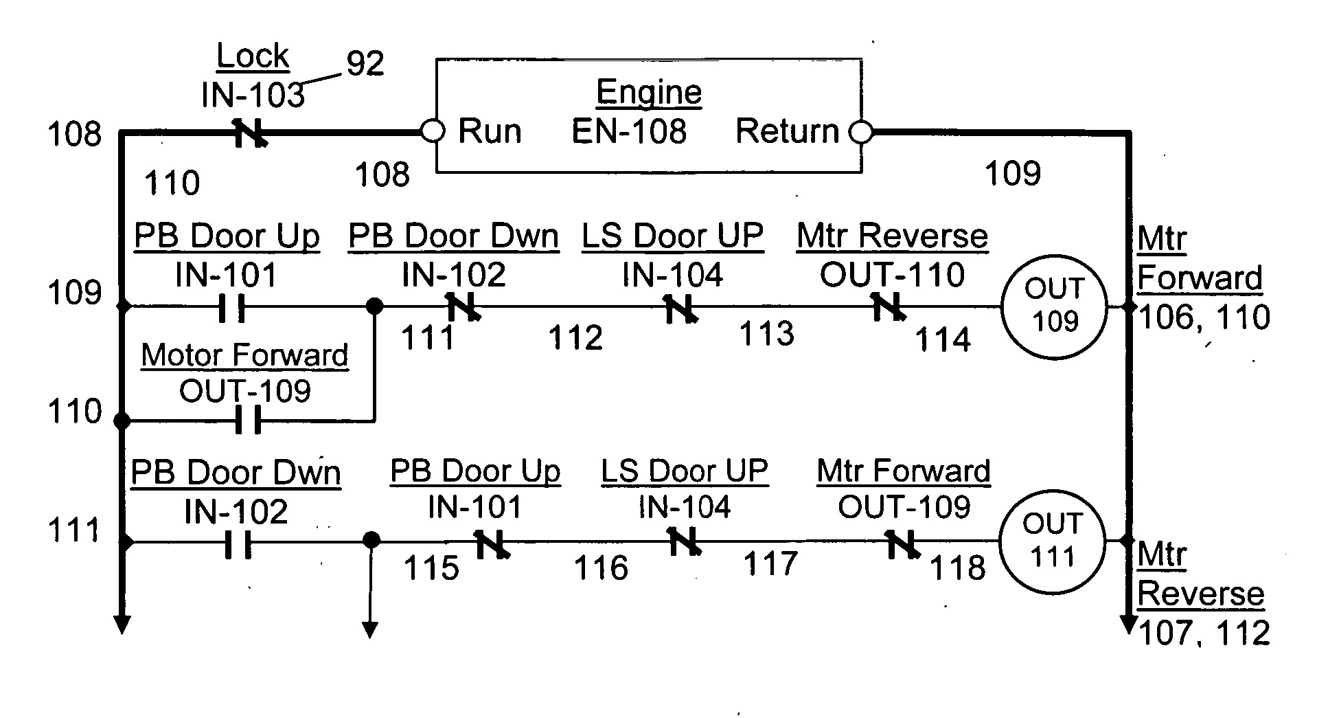
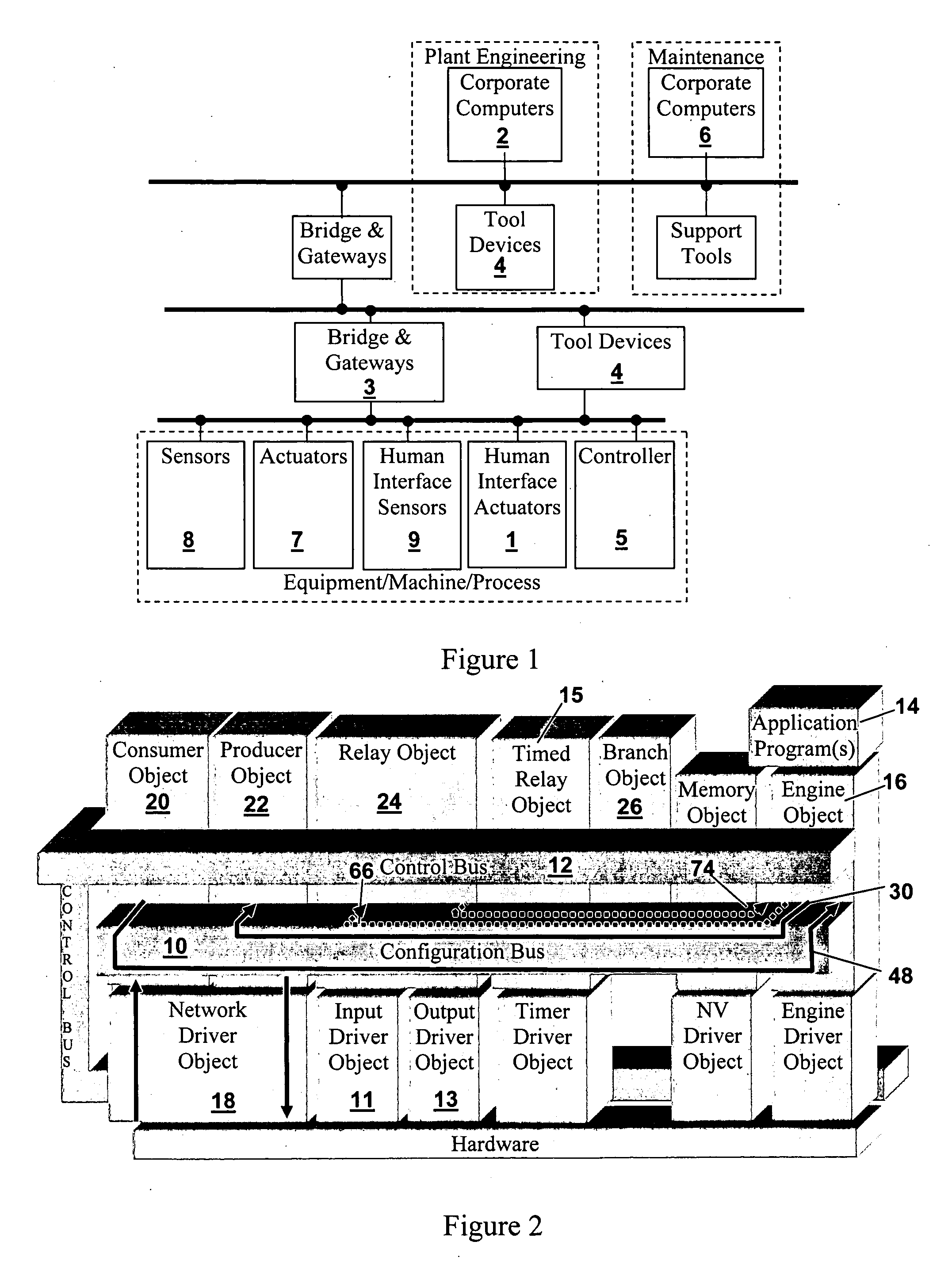
[0004] The present invention comprises a consistent System Architecture composed of an System Architecture, Control Apparatus Architecture, Tool Device Architecture and Information Interface Architecture that provide a common interface across different types of Control Devices and across different systems, networks and applications. The programming method for all Control Apparatus, whether communicating or not communicating, is independent of the specific hardware platforms they represent and the network used to interconnect and program these Control Apparatus. The architecture allows the creation of a Control Devices by utilizing sets of standardized software objects, where the product functionality is determined by engaging functions within these objects and interconnecting the internal objects in accordance with the instructions in application program(s) that are executed by a special application execution engine on each device. The software application objects, application program and application engine provide a virtual system for and by which Control Apparatus can be programmed using a common tool via a standard interface where common application programs can be generated which are portable and capable of running on different Control Apparatus. This invention also defines an Object, Control Apparatus, Tool Device and System architecture where schematic design tool paradigms may be used to view, program and interconnect control logic, wiring, and hardware within a Control Apparatus to define the Control Apparatus behavior and target application behavior, as well as interconnect objects between Control Apparatus to create system behavior.

Problems solved by technology

The functionality provided to the control system by the devices is limited by the software included with each control device where such product specific programming tools as may exist allow the limited configuration of the delivered device functionality.
Although some attempts have been to define user interface standards, they are limited to single types of devices (IEC 1131 programmable controller) and solely include instructions specific to those devices.
Although a step in the right direction, the programs can not be transferred and loaded into products from different vendors.
Since many programs for control devices are custom developed from scratch, in practice it is a challenging, burdensome, and time consuming job to program these types of control systems and the programs produced often require substantial debugging with multiple, device specific tools.
Maintenance and support are equally challenging since available tools are, again, limited and there are little or no reliable organizational principles governing the structures of control device software and firmware.

Method used


Image

  • Architecture for control systems
  • Architecture for control systems
  • Architecture for control systems

Examples


Embodiment Construction

[0059] This invention defines the internal Control Apparatus architecture and network interface architecture within a Control Apparatus required to achieve a common control, information and network architecture from a simple Control Apparatus without a network interface up through a highly functional and complex fully programmable Control Apparatus that supports multiple networks and contains numerous forms of inputs and outputs and includes interfaces to enterprise level information management systems.

[0060] This invention defines a Tool Device architecture that contains all the functionality of the Control Apparatus architecture and extends the core functionality to support Software Tool Device applications and extends the Control Apparatus and Tool Device external interface dialogs to include a common external interface to the enterprise level system information management systems. This invention defines a System Architecture, where the Tool Device Architecture and Control Appar...


PUM


Abstract

An architecture for control systems including multiple control devices. The control devices include standardized software objects having functions, application programs for engaging these functions and thereby defining the operation of the control devices, and an engine for executing the application programs. The standardized software objects implement different types of internal functions for the control devices and feature reference numbering and function calls shared in common with the other software objects of the same type that may be on different control devices across said system. The software application programs include standardized instructions reflecting the reference numbering and function calls shared across the system by the said software objects whose functions are used in building the functionality of the control devices in the application programs.

Description

[0001] This patent application claims the benefit of Provisional Patent Application Ser. No. 60 / 638,939 filed Dec. 24; 2004, Provisional Patent Application Ser. No. 60 / 638,690 filed Dec. 24, 2004 and Provisional Patent Application Ser. No. 60 / 638,684 filed Dec. 24, 2004 all filed with the United States Patent and Trademark Office.TECHNICAL FIELD [0002] The field of the present invention is control systems and more particularly architectures for control systems and especially control systems allowing for application programs to be used across different hardware platforms. BACKGROUND OF THE INVENTION [0003] Most control systems operate over a number of different control devices each of which represents a different type of hardware platform featuring its own unique hardware and software environment. Each control device requires custom programming to make the device function and operate as a component of the system. The functionality provided to the control system by the devices is limi...

Claims


Application Information

Patent Timeline
Patent Type & Authority Applications(United States)
IPC IPC(8): G05B15/00
CPCG05B19/042G05B19/056G05B2219/13101G05B2219/13144G05B2219/13148G05B2219/15012G05B2219/23255G05B2219/25009G05B2219/25232
Inventor PIERONEK, DONALD
Owner PIERONEK DONALD
Learn More