System and method of determining the speed of digital application specific integrated circuits

a technology of integrated circuits and speed determination, applied in the direction of electric digital data processing, measurement of structures/machines, instruments, etc., can solve the problem that integrated circuits do not have the ability to communicate their running speed

Inactive Publication Date: 2006-07-13
INST OF COMP SCI FOUND FOR RES TECH - HELLAS ICS
View PDF14 Cites 16 Cited by
  • Summary
  • Abstract
  • Description
  • Claims
  • Application Information

AI Technical Summary

Benefits of technology

[0014] The above embodiment may have various optional features. A plurality of synchronous circuit elements may be configured to receive at least a portion of output data from the plurality of logic circuits, respectively, and configured to be clock driven by a clock signal from the plurality of variable clock generators, respectively. The plurality of synchronous circuit elements may be flip-flops. A variable power supply may be configured to power the multi-rail monotonic circuit, such that a running speed of the circuit increases in response to increases in the variable power supply, and decreases in response to decreases in the variable power supply. Each of the plurality of delay circuits may have a delay that is greater than a maximum processing time of respective ones of the plurality of logic circuits, as well as substantially equal to the maximum processing time of respective ones of the plurality of logic circuits.

Problems solved by technology

Currently manufactured IC's do not have the ability to communicate their running speed.

Method used


Image

  • System and method of determining the speed of digital application specific integrated circuits
  • System and method of determining the speed of digital application specific integrated circuits
  • System and method of determining the speed of digital application specific integrated circuits

Examples


Embodiment Construction

[0023] The particulars shown herein are by way of example and for purposes of illustrative discussion of the embodiments of the present invention only and are presented in the cause of providing what is believed to be the most useful and readily understood description of the principles and conceptual aspects of the present invention. In this regard, no attempt is made to show structural details of the present invention in more detail than is necessary for the fundamental understanding of the present invention, the description taken with the drawings making apparent to those skilled in the art how the several forms of the present invention may be embodied in practice.

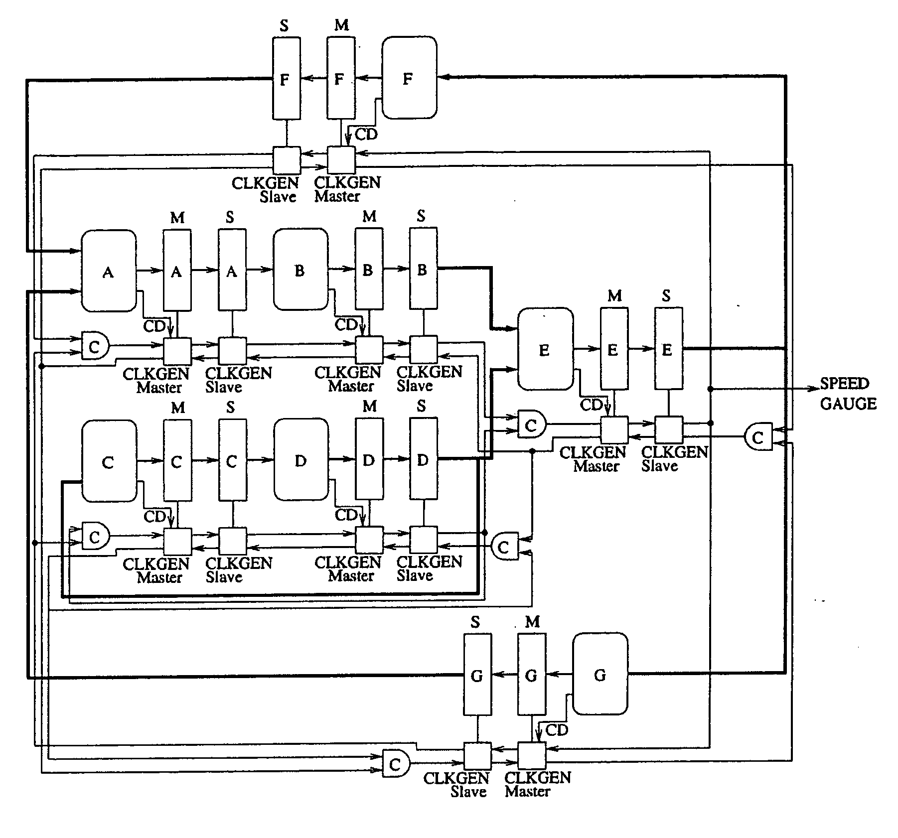
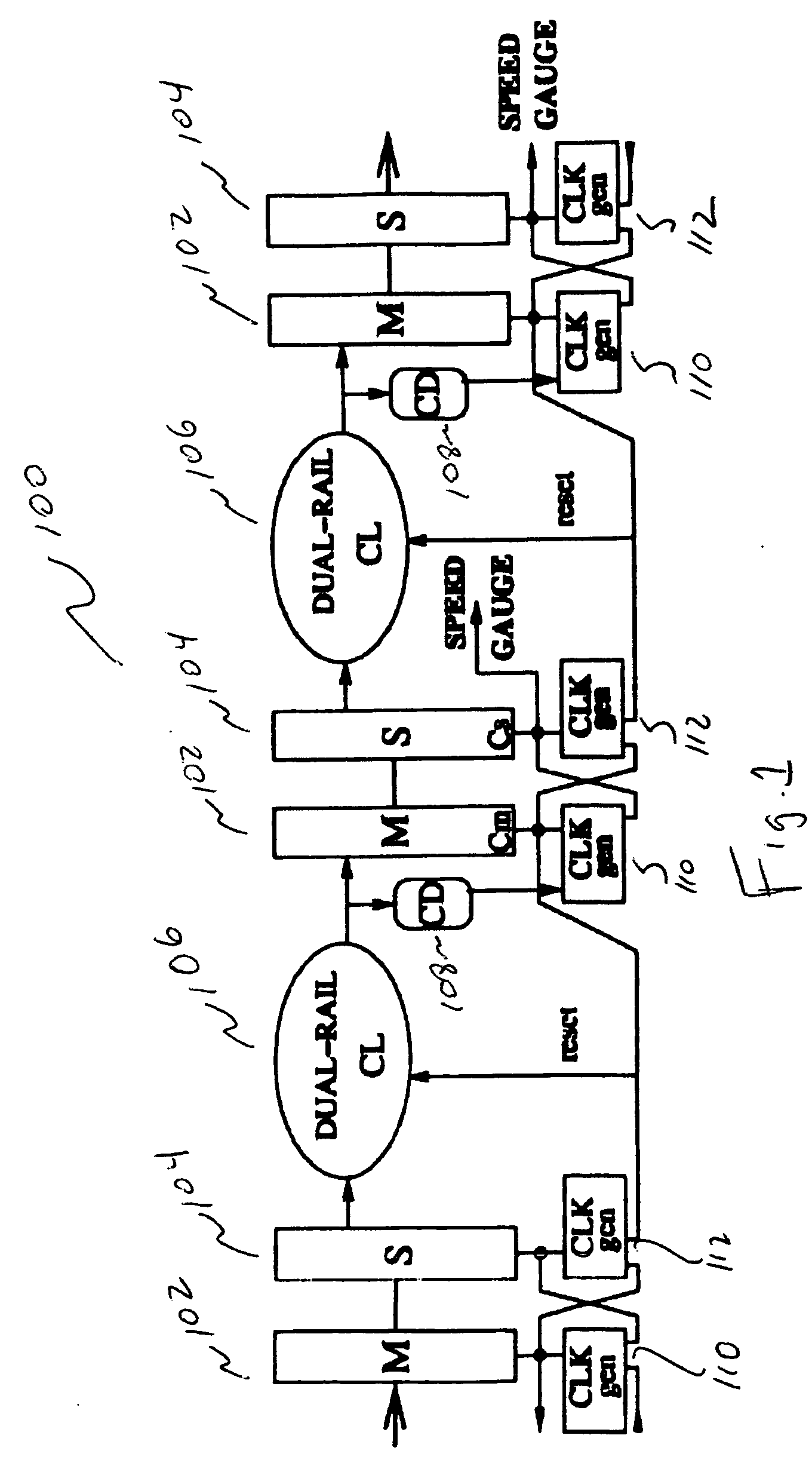
[0024] Referring now to FIG. 1, an embodiment of the invention is shown in a linear pipeline structure collectively as circuit 100. A master flip-flop 102 receives input data from an upstream source. The data passes to a slave flip-flop 104, which in turn passes the input data to a circuit cloud 106. Circuit cloud 106 i...


PUM


Abstract

According to one embodiment of the present invention, a system for identifying a running speed of an integrated circuit is provided. An asynchronous multi-rail circuit is configured to receive input data and transmit output data. A completion detection circuit is configured to generate a completion detection signal for the asynchronous multi-rail circuit. A variable clock generator configured to be driven by at least the completion detection signal. A synchronous circuit element configured to receive at least a portion of the output data and configured to be clock driven by a clock signal from the variable clock generator. A period of the clock signal represents a running speed of the asynchronous circuit.

Description

CROSS-REFERENCE TO RELATED APPLICATIONS [0001] The present application is a continuation-in-part of U.S. patent application Ser. No. 11 / 283,070, filed on Nov. 21, 2005, which claims priority under 35 U.S.C. § 120 to U.S. Provisional Patent Application Ser. No. 60 / 642,990, filed on Jan. 12, 2005, the disclosures of which are expressly incorporated by reference herein in their entirety.BACKGROUND OF THE INVENTION [0002] 1. Field of the Invention [0003] The present invention relates to determining the running speed of an integrated circuit. More specifically, the present invention relates to an integrated circuit with an internal clocking system where the clock period represents the speed of the clocked circuit. [0004] 2. Discussion of Background Information [0005] Integrated circuits made according to the same manufacturing process are typically not created equal. Due to various imperfections in the manufacturing process from one lot of chips to the next, and even with the same lots, ...

Claims


Application Information

Patent Timeline
Patent Type & Authority Applications(United States)
IPC IPC(8): G06F1/06G01M99/00
CPCG01R31/3016G01R31/31718G01R31/31725
Inventor SOTIRIOU, CHRISTOS P.
Owner INST OF COMP SCI FOUND FOR RES TECH - HELLAS ICS
Why Eureka
Try Eureka