Remote viewing system

a remote viewing and viewing system technology, applied in the field of remote viewing systems, can solve the problems of affecting the overall appearance of the entryway, and requiring installation and maintenan

Inactive Publication Date: 2006-07-13
PLASTPRO 2000
View PDF7 Cites 282 Cited by
  • Summary
  • Abstract
  • Description
  • Claims
  • Application Information

AI Technical Summary

Benefits of technology

[0006] A system is disclosed for providing video and/or audio data to a monitoring station. Preferably the system comprises a video camera, with an optional microphone, both of which are disposed within the panels of a standard entryway door. Additionally the system can comprise appropriate electronics for processing, storing, and transmitting the video and/or audio data to a remote location. The video camera and associated wiring can be located within the door itself, and the processing electronics can be located adjacent to the door either on or in the wall structure. Alternatively, the electronics can also be located within the door panels so as to be hidden from the outside of the door. Data transmission can be via hard wiring that is run directly from the door to the monitoring

Problems solved by technology

Such systems, while effective, suffer from various practical deficiencies in that they can be expensive to install and maintain.
Additionally, wall mounted video cameras may suffer from certain aesthetic liabilities, in that they can detract from the overall appearance of the entryway, such as where the building is a home or office

Method used


Image

  • Remote viewing system
  • Remote viewing system
  • Remote viewing system

Examples


Embodiment Construction

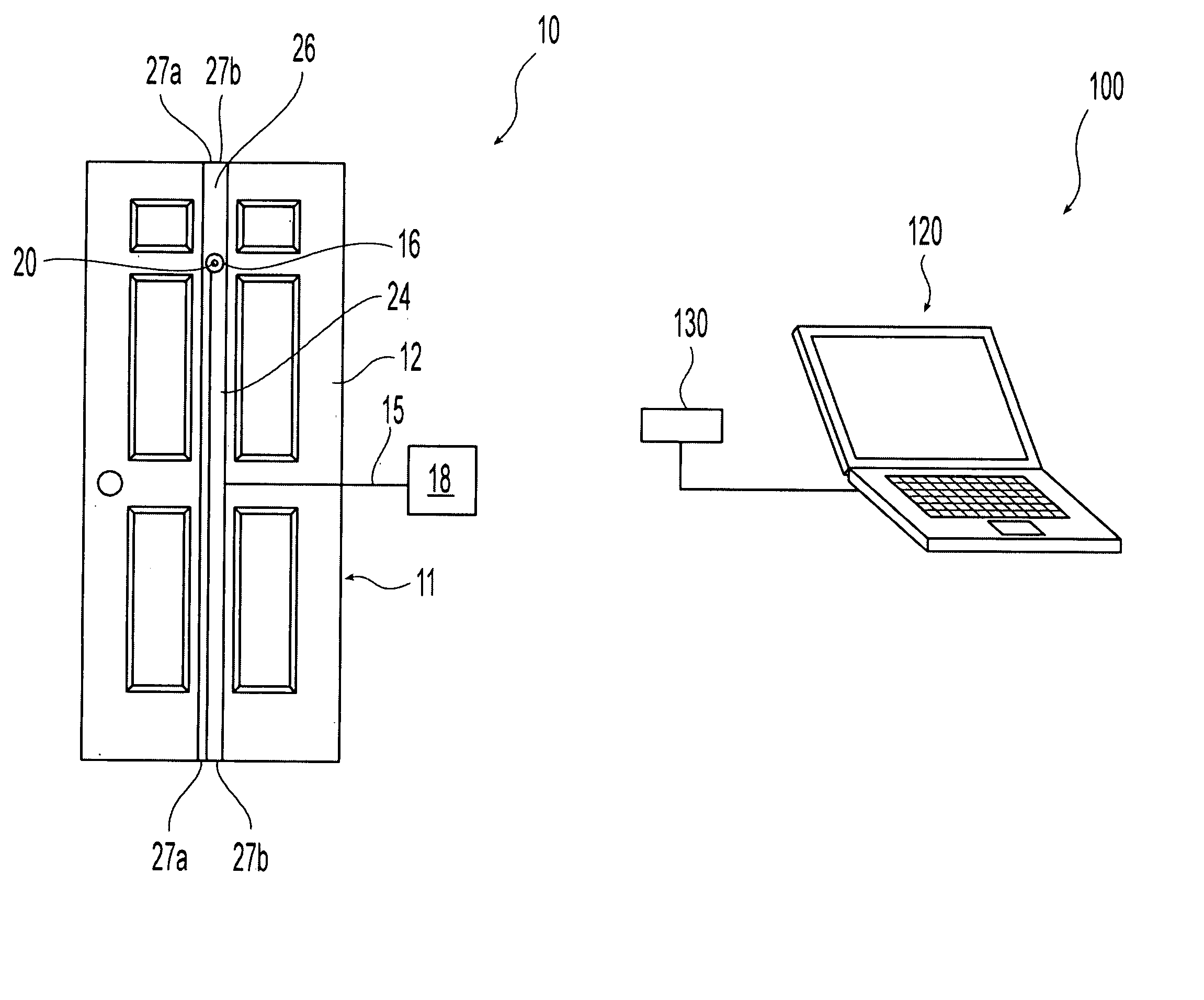
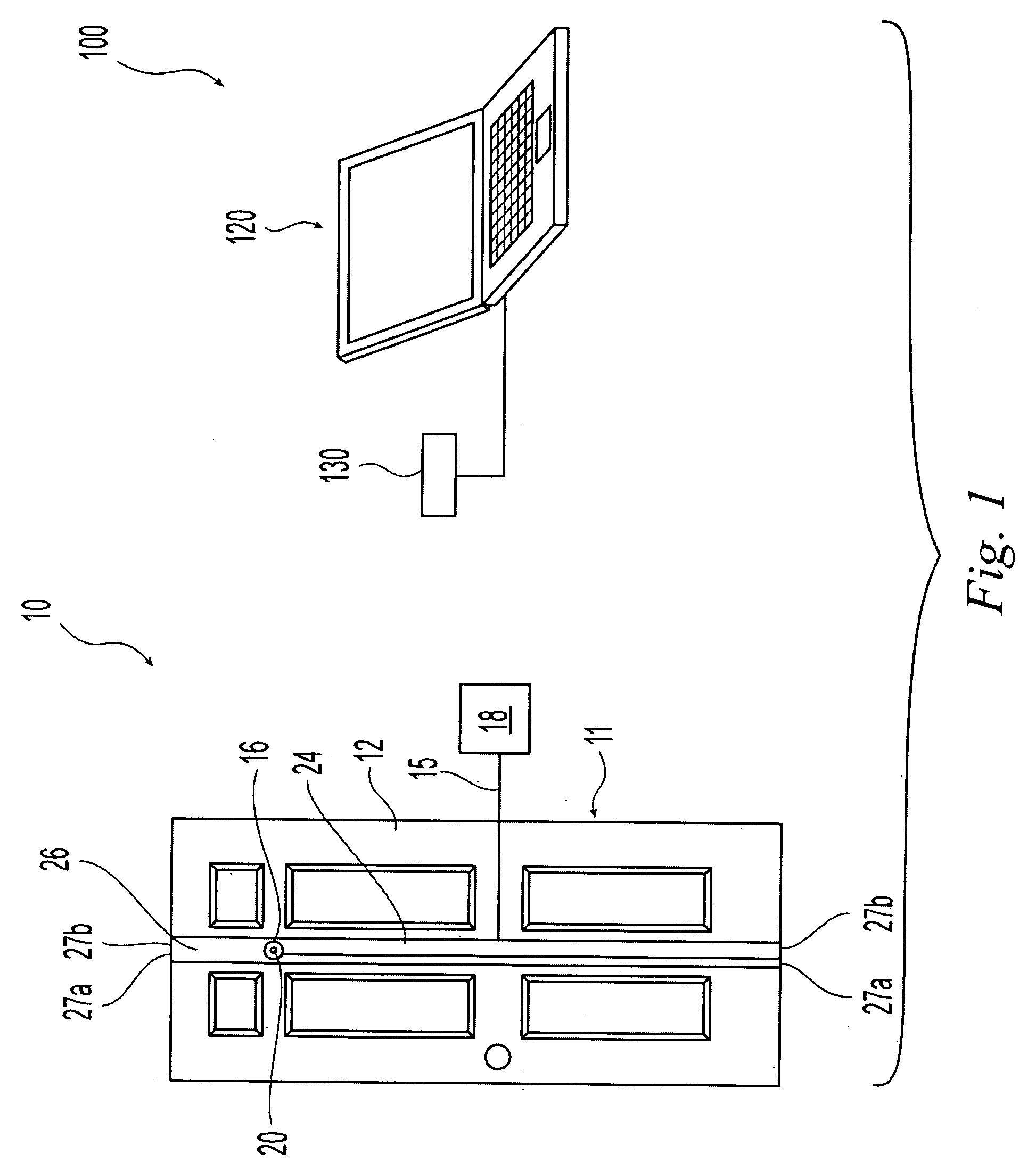
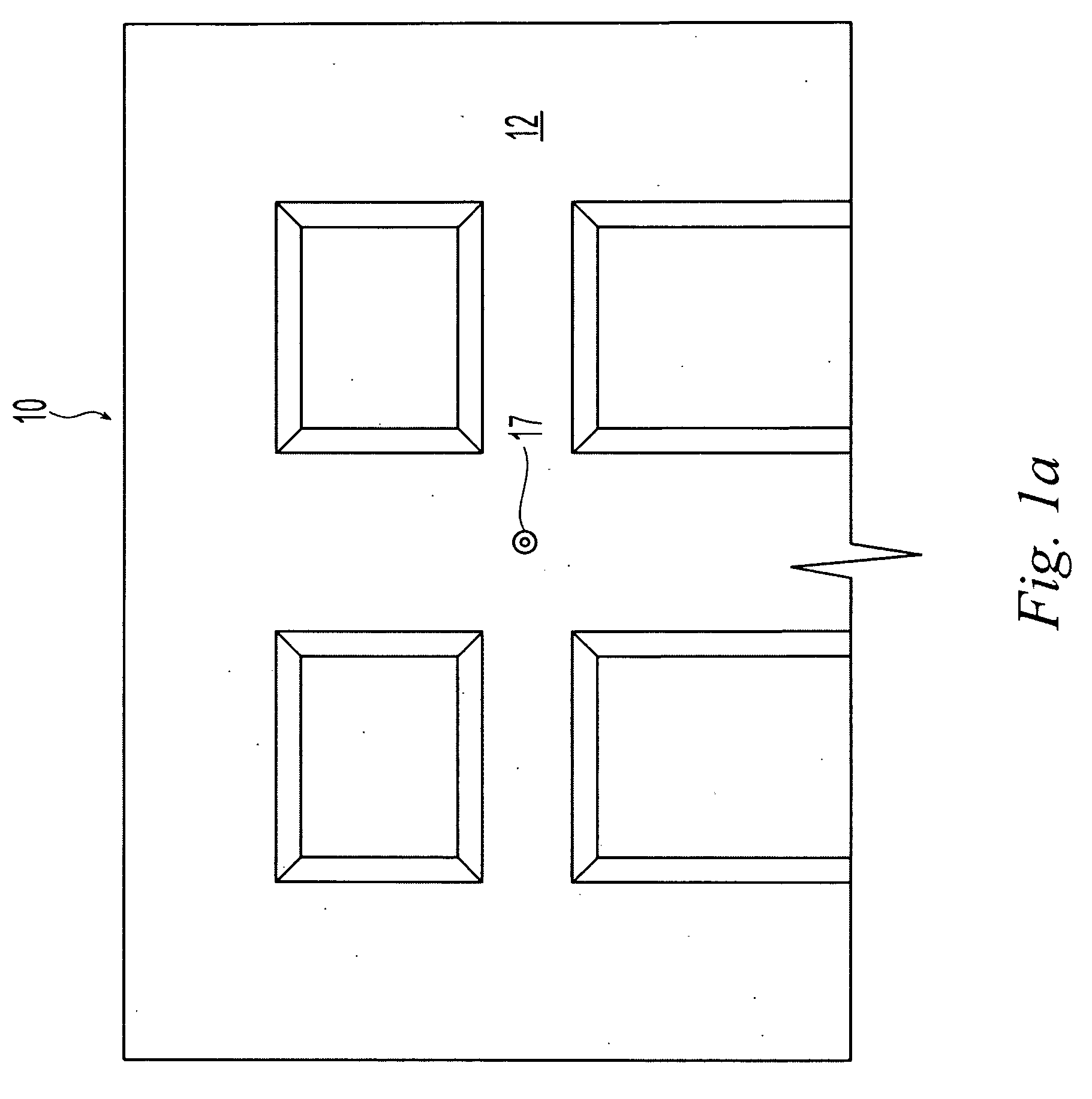
[0017] This invention is directed to a system for providing remote monitoring of a doorway or entryway, in which a substantial portion of the system can be installed within the panels of the door itself, thus rendering it unnoticeable from the exterior (as well as the interior) of the door. The system can be installed in any of a variety of standard door sizes, thus allowing a user to install the system with a minimum of disruption to the surroundings.

[0018] Referring to FIG. 1, an exemplary door unit 10 and remote viewing station 100 are shown. The door unit 10 can comprise first and second door panels 12, 14, and a video camera 16 disposed therebetween. The video camera 16 can be wireless or Bluetooth compatible, and can be controlled using a wireless driver 18 (FIG. 3), such as a Bluetooth driver located adjacent to the door 10. The wireless driver 18 can power the camera 16, and can process the video data provided from the camera 16 and transmit that processed data to the remot...


PUM


Abstract

A remote viewing system is disclosed for providing video and/or audio surveillance of an entry or doorway of a building. The system is provided within the panels of the entry or doorway door. A video camera is positioned within the panels to obtain video images of the entryway or doorway and to transmit them via Bluetooth wireless connection to a remote viewing station. The Wireless driver for the camera can be located in or adjacent to the door panel. Video and audio data can be transmitted from the driver to any of a variety of Bluetooth enabled electronic devices, including PCs, PDAs, cell phones, and the like.

Description

CROSS-REFERENCE TO RELATED APPLICATION [0001] This is a non-provisional application of pending U.S. provisional patent application Ser. No. 60 / 643,304, filed Jan. 12, 2005, by Wang et al., titled “Remote Viewing System,” the entire contents of which is incorporated by reference herein.FIELD OF THE INVENTION [0002] This invention relates to a remote viewing system, and more particularly to a viewing system that can be installed within the structure of a door for observation of the surrounding area from a remote location. BACKGROUND OF THE INVENTION [0003] A wide variety of security systems exist to provide audio and video surveillance of entrance areas of buildings. Such systems can consist of wall mounted video cameras and intercom systems that allow a person inside the building to monitor the exterior of the building and to admit or deny entry based on the information obtained from the audio or video data. For example, an external security door in a building can have a wall mounted...

Claims


Application Information

Patent Timeline
IPC IPC(8): H04N7/173H04N7/18H04N9/47
CPCH04N7/186
Inventor WANG, WALTER W.WANG, SHIRLEYAN, PAO YU
Owner PLASTPRO 2000
Why Eureka
Try Eureka