Reception device and setting method thereof

a technology of a reception device and a setting method, which is applied in the field of reception devices, can solve the problems of not being able to easily judge which frequency, the frequency data contained in the broadcast signals becomes no longer in agreement with the frequency of signals really transmitted through the cable, and the inability to transmit signals through one cable by simply mixing all signals together, etc., to achieve the effect of promoting retrial and increasing channels

Inactive Publication Date: 2006-07-13
SONY CORP
View PDF12 Cites 10 Cited by
  • Summary
  • Abstract
  • Description
  • Claims
  • Application Information

AI Technical Summary

Benefits of technology

[0030] This promotes the retrial upon

Problems solved by technology

In redelivering the signals by the community receiving system, the bands of intermediate-frequency signals are overlapped between the BS broadcast and the CS broadcast, making it impossible to transmit the signals through one cable by simply mixing all signals together.
When the modulation conversion system is employed for the community receiving system, however, the channel is converted into a channel of a frequency different from that of the channel u

Method used


Image

  • Reception device and setting method thereof
  • Reception device and setting method thereof
  • Reception device and setting method thereof

Examples


Embodiment Construction

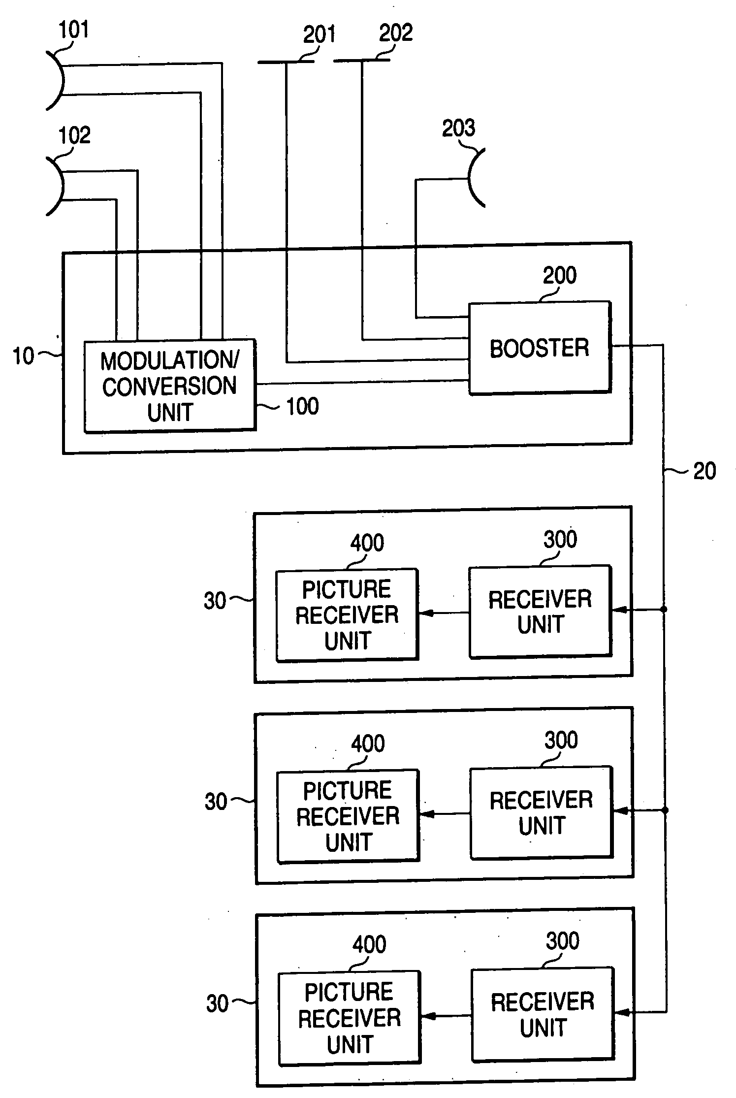
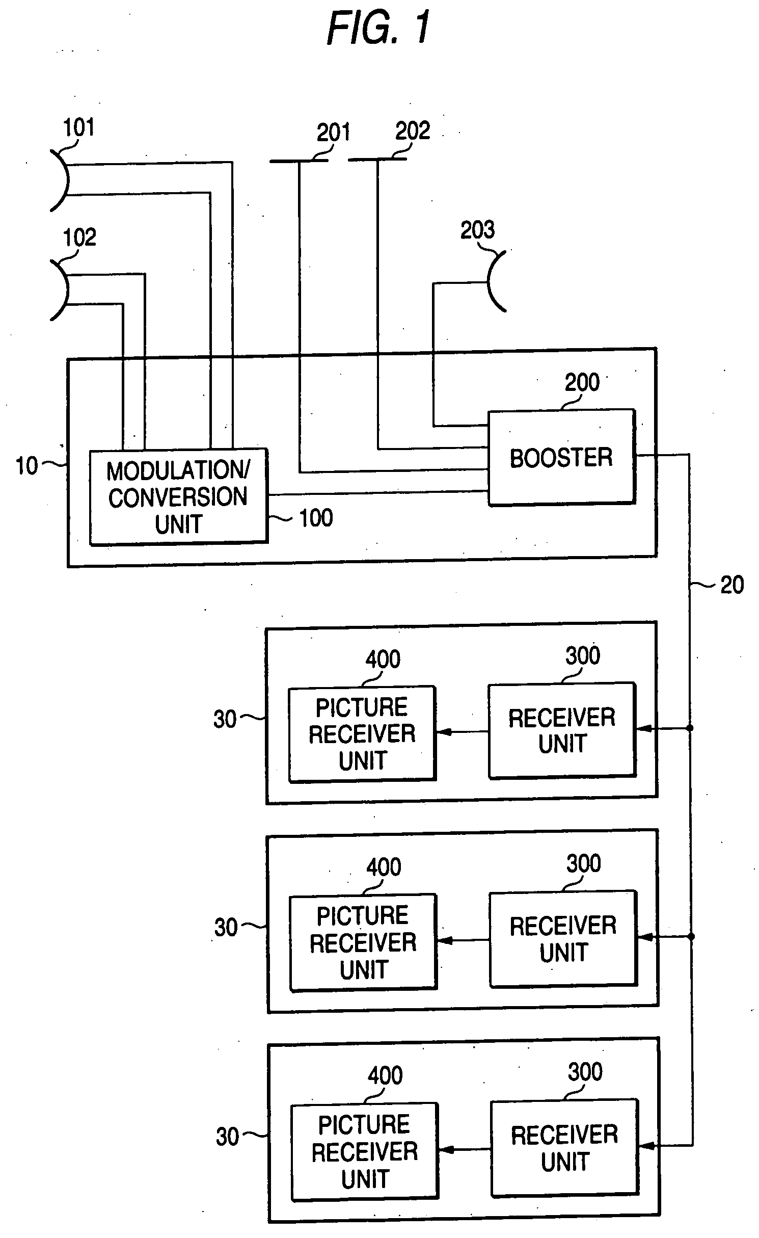
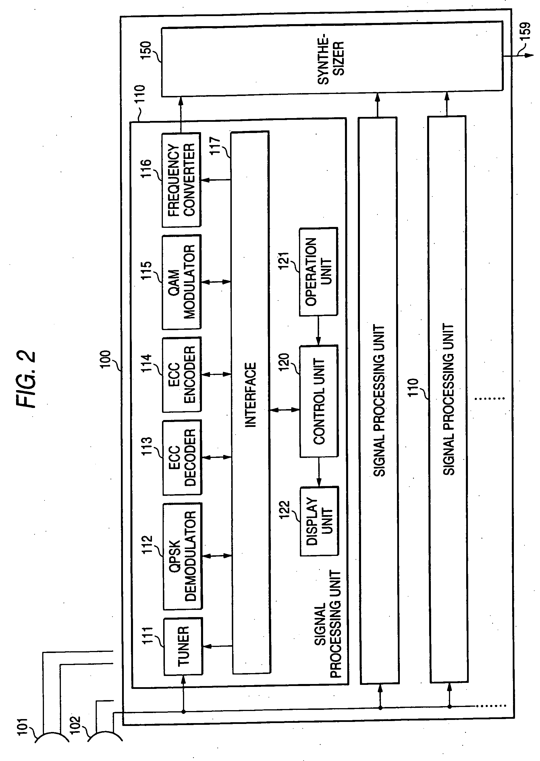
[0116]FIG. 1 is a diagram illustrating a community receiving system according to an embodiment of the invention. The community receiving system according to the embodiment of the invention includes a community redelivering facility 10 for receiving the broadcast and redelivering the signals to the households, a cable 20 for transmitting the signals redelivered from the community redelivering facility 10 to the households, and receiving facilities 30 in the households. To the community redelivering facility 10 are connected a VHF antenna 201 for receiving VHF broadcast, a UHF antenna 202 for receiving UHF broadcast, a BS antenna 203 for receiving BS broadcast, and CS antennas 101 and 102 for receiving CS broadcast. The community redelivering facility 10 includes a modulation / conversion unit 100 for modulating and converting the signals of CS broadcast, and a booster 200 for mixing the signals together. Further, each receiving facility 30 includes a receiver unit 300 for receiving the...


PUM


Abstract

Satellite receiving channel data 810 are described in a network information table (NIT) in a random fashion. Frequencies in the redelivering facility in a community receiving system are arranged in order of increasing frequencies for each of the networks. In a receiver unit, the frequencies 753 of the satellite receiving channel data 810 are rearranged in order of increasing frequencies and are registered to the receiving frequencies 831 in a frequency conversion table 830. The receiver unit selects the frequency according to wire frequencies 822 of a wire channel 821 in a wire frequency table 820 and registers the wire frequency of a channel that can be normally received to a conversion frequency 832 in the frequency conversion table 830. Therefore, the frequency data contained in the broadcast signals before being redelivered are corresponded to the redelivering frequency of signals really transmitted through a cable on the receiver unit side in the community receiving system.

Description

TECHNICAL FIELD [0001] This invention relates to a receiver unit and a method of setting the same. More specifically, the invention relates to a receiver unit for receiving broadcast signals redelivered in a community receiving system of a satellite broadcast, to a processing method in the receiver unit, to a program which so works that a computer executes the above method, and to a recording medium for recording the program. BACKGROUND ART [0002] Apartment houses are using a community receiving system having a community antenna and in which broadcast signals received by the community antenna are redelivered to each household. It is expected that the community receiving system delivers analog signals of a ground wave broadcast in the VHF (very-high frequency) band and in the UHF (ultra-high frequency) band, as well as digital broadcast signals of a broadcast satellite (BS) and a communication satellite (CS). [0003] In redelivering the signals by the community receiving system, the b...

Claims


Application Information

Patent Timeline
IPC IPC(8): H04N7/173H04N7/16H04N5/44H04N5/40H04H20/00H04H20/02H04H20/06H04N5/00H04N7/10H04N7/20H04N21/438H04N21/442
CPCH04H20/02H04H20/06H04N7/10H04N7/20H04H20/20H04N5/44
Inventor OISHI, KATSUMI
Owner SONY CORP
Why Eureka
Try Eureka