
Grease extraction system, particulate extractor, and method

Inactive Publication Date: 2006-07-20
HEILMAN NIKOLAUS J
View PDF13 Cites 48 Cited by
  • Summary
  • Abstract
  • Description
  • Claims
  • Application Information

AI Technical Summary

Benefits of technology

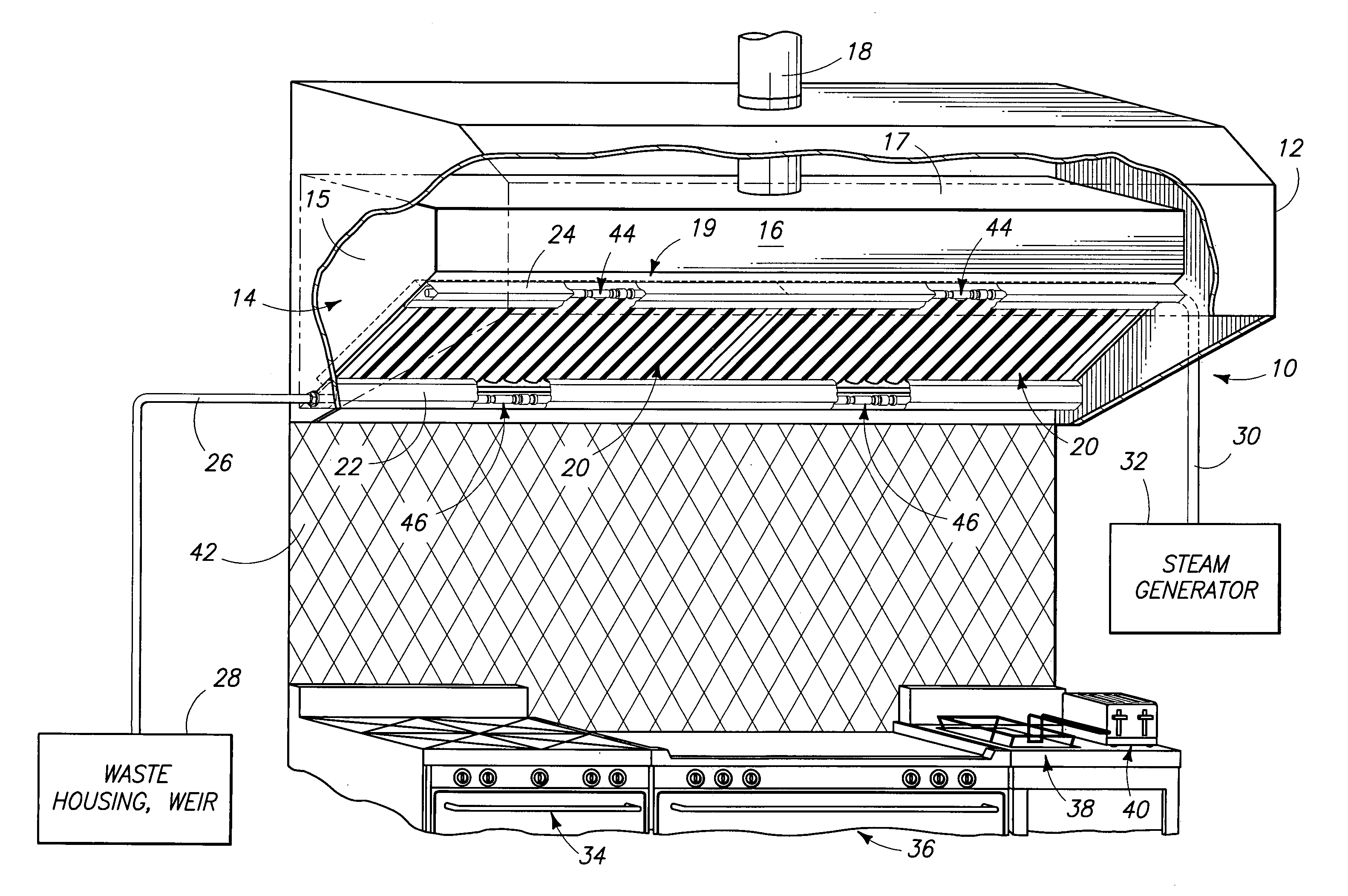
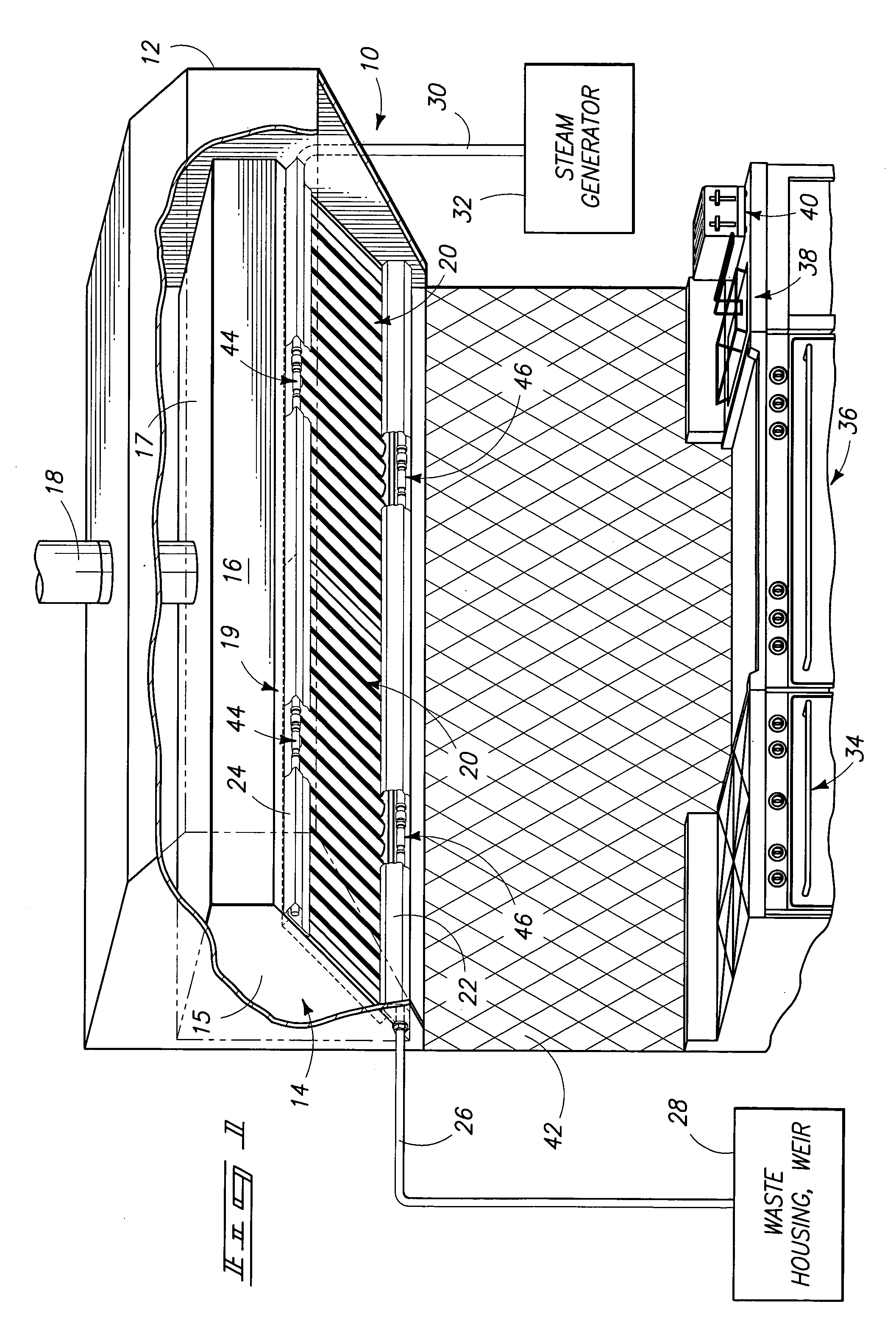
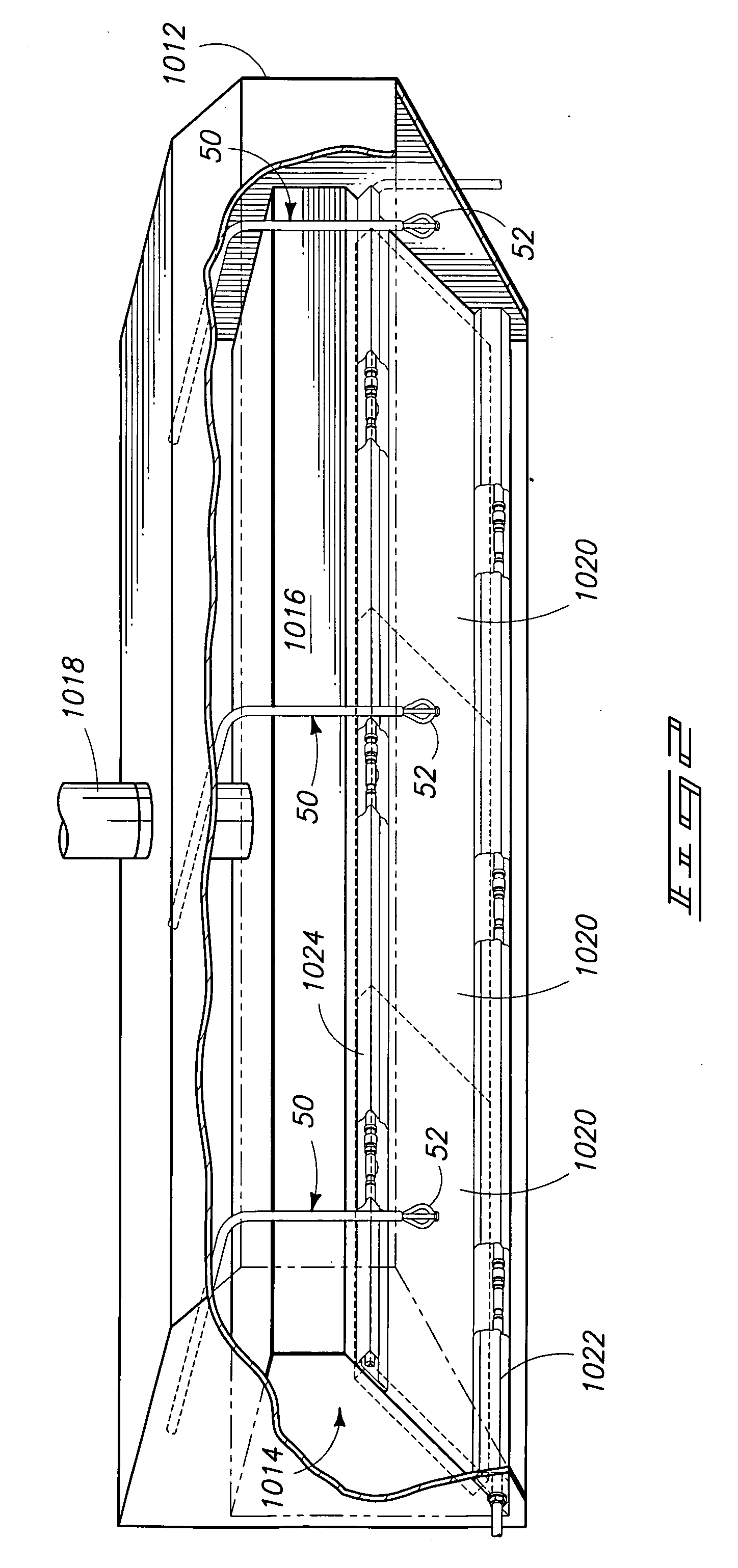
[0006] A highly efficient grease extractor includes multiple arrays of baffle plates that are configured to provide a circuitous path in combination with a steam ejector in order to generate more efficient and effective extraction of grease from ventilated cooking gases and air.
[0010] One advantage is provided by more efficient and thorough extraction of grease from exhaust fumes entering a kitchen ventilation system.

Problems solved by technology

However, porous filter-type grease extractors tend to be relatively inefficient at extracting grease from contaminated air in an exhaust hood.
Hence, grease is typically carried into exhaust ducts and components of the exhaust hood, which reduces airflow over time and creates a potential fire hazard.
Secondly, the screens tend to clog, and they have to be removed and cleaned periodically.
The baffles creates a circuitous airflow paths that redirect and divert exhaust air that is being drawn into an exhaust hood which causes grease and contaminants to be deposited onto the interior surfaces of the baffles.
However, the circuitous paths do not trap enough of the grease, in many cases, more than half of the grease may still pass through the grease extractor and up into the ventilation system of the hood, including the airflow ducts and hood.
This has an undesirable effect of reducing airflow and efficiency of the ventilation system.
Secondly, buildup of grease within the ventilation system, downstream of the baffles, increases a risk of fires in the ventilation system.

Method used


Image

  • Grease extraction system, particulate extractor, and method
  • Grease extraction system, particulate extractor, and method
  • Grease extraction system, particulate extractor, and method

Examples


Embodiment Construction

[0034] This disclosure of the invention is submitted in furtherance of the constitutional purposes of the U.S. Patent Laws “to promote the progress of science and useful arts” (Article 1, Section 8).

[0035] Reference will now be made to preferred embodiments of Applicant's invention comprising grease extractors for use with kitchen ventilation systems over kitchen ranges, grills, griddles, and / or fryers. While the invention is described by way of preferred embodiments, it is understood that the description is not intended to limit the invention to such embodiments, but is intended to cover alternatives, equivalents, and modifications which may be broader than the embodiments, but which are included within the scope of the appended claims.

[0036] In an effort to prevent obscuring the invention at hand, only details germane to implementing the invention will be described in great detail, with presently understood peripheral details being attached as an appendix, as needed, as being pr...


PUM


Abstract

A grease extractor is provided with a frame, a first array of convex baffle plates, a second array of concave baffle plates, and a steam ejector. The first array of convex baffle plates is carried by the frame in spaced-apart relation, so as to provide a first ventilation slot between adjacent, convex baffle plates. The second array of concave baffle plates is carried by the frame in spaced-apart relation, so as to provide a second ventilation slot between adjacent, concave baffle plates. A selected one of the concave baffle plates is offset from a respective, downstream convex baffle plate such that the first ventilation slot opens into a base portion of the concave baffle plate. The steam ejector is supported proximate each ventilation slot for delivering steam into the first ventilation slot and toward a respective one of the concave baffle plates. A method is also provided.

Description

RELATED PATENT DATA [0001] This application claims priority from U.S. Provisional Patent Application Ser. No. 60 / 637,264, which was filed Dec. 17, 2004, and which is incorporated by reference herein.TECHNICAL FIELD [0002] The present invention pertains to kitchen ventilation systems. More particularly, the present invention relates to grease extractors for kitchen ventilating systems, such as kitchen exhaust hood assemblies. BACKGROUND OF THE INVENTION [0003] It is previously known to use porous filter-type grease extractors supported within a frame to extract grease from contaminated air that is being drawn into a kitchen exhaust hood assembly. One such construction uses a metal mesh that is contained within an outer peripheral frame to provide a modular grease filter for an exhaust hood. However, porous filter-type grease extractors tend to be relatively inefficient at extracting grease from contaminated air in an exhaust hood. Hence, grease is typically carried into exhaust ducts...

Claims


Application Information

Patent Timeline
IPC IPC(8): F24C15/20
CPCF24C15/2035
Inventor HEILMAN, NIKOLAUS J.
Owner HEILMAN NIKOLAUS J
Learn More