
Parallel cigarette filter combining techniques with particle filling of cavities

a technology of cigarette smoke filter and cavity, which is applied in the field of parallel cigarette smoke filter combining techniques with cavity filling, can solve the problems of incomplete serial stream incomplete cigarette smoke filter, etc., and achieves the effect of reducing manpower requirements, reducing production costs, and improving quality

Active Publication Date: 2006-07-20
PHILIP MORRIS USA INC
View PDF9 Cites 66 Cited by
  • Summary
  • Abstract
  • Description
  • Claims
  • Application Information

AI Technical Summary

Benefits of technology

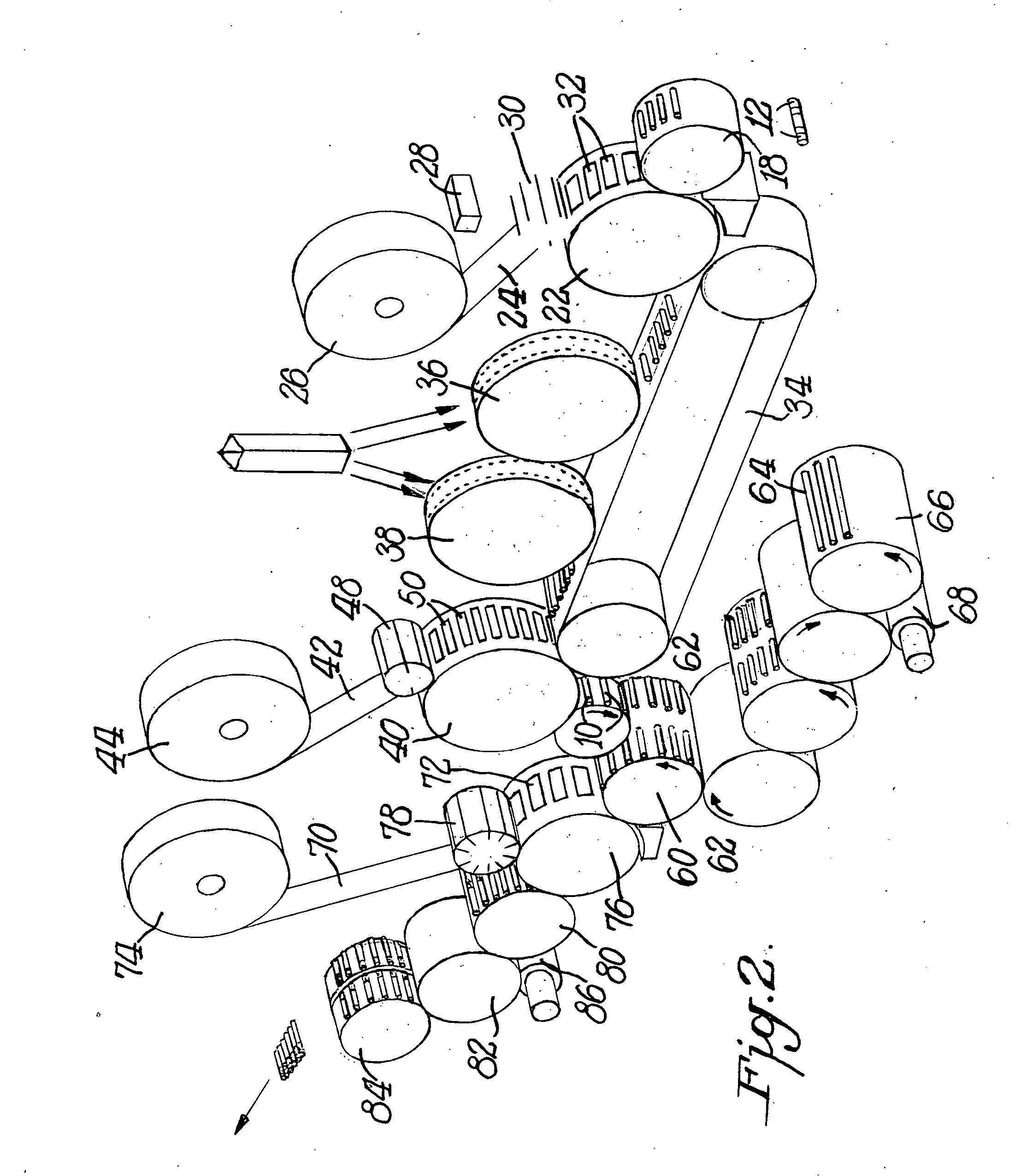
The present invention provides a new equipment group that can make a combined cigarette filter with cavities filled with particles. The filter components are assembled, wrapped with paper, and the cavities are filled in a parallel method. This invention results in higher quality, faster processing, reduced labor and material waste. Additionally, a second embodiment merges this combining technology into the cigarette assembly process to combine filters, fill the cavities with particles, and then merge the filter assembly with the tobacco rod component to complete the cigarette construction, all in one equipment grouping or module.

Problems solved by technology

One of the limitations of the prior technologies used to combine filter components is the registration (positions) of the components to each other as well as to the final cut of the filter assembly.
The process of transferring multiple components into the serial stream often results in unintentional gaps, components having the wrong lengths, or the total lack of a component being present.
In addition to these issues, once the serial filter assembly is wrapped and sealed in a paper, the continuous serial filter assembly is then cut into lengths.
In prior processes, unintentional gaps between filter components cause the entire serial stream to change position and could affect the final cut registration.
Furthermore, according to prior techniques for the filling of cavities, the possibility of these particles ending up trapped outside the pocket region but under the filter wrap exceeds acceptable limits.
Both of these methods are expensive, increase production waste, and complicate the entire manufacturing process.
While it is not guaranteed that all of the particles transferred from the drum end up in the cavity, there is no area where the particle can come to rest on the surface of the filter assembly.
Prior methods for the assembly of combined filters are also limited by several factors relating to productivity.
Using a typical 108 millimeter filter as an example, these prior processes can produce 1,900 to 3,800 filter assemblies per minute, the limiting factor being the ability to deliver particles from the delivery drum to the cavities.

Method used


Image

  • Parallel cigarette filter combining techniques with particle filling of cavities
  • Parallel cigarette filter combining techniques with particle filling of cavities
  • Parallel cigarette filter combining techniques with particle filling of cavities

Examples


Embodiment Construction

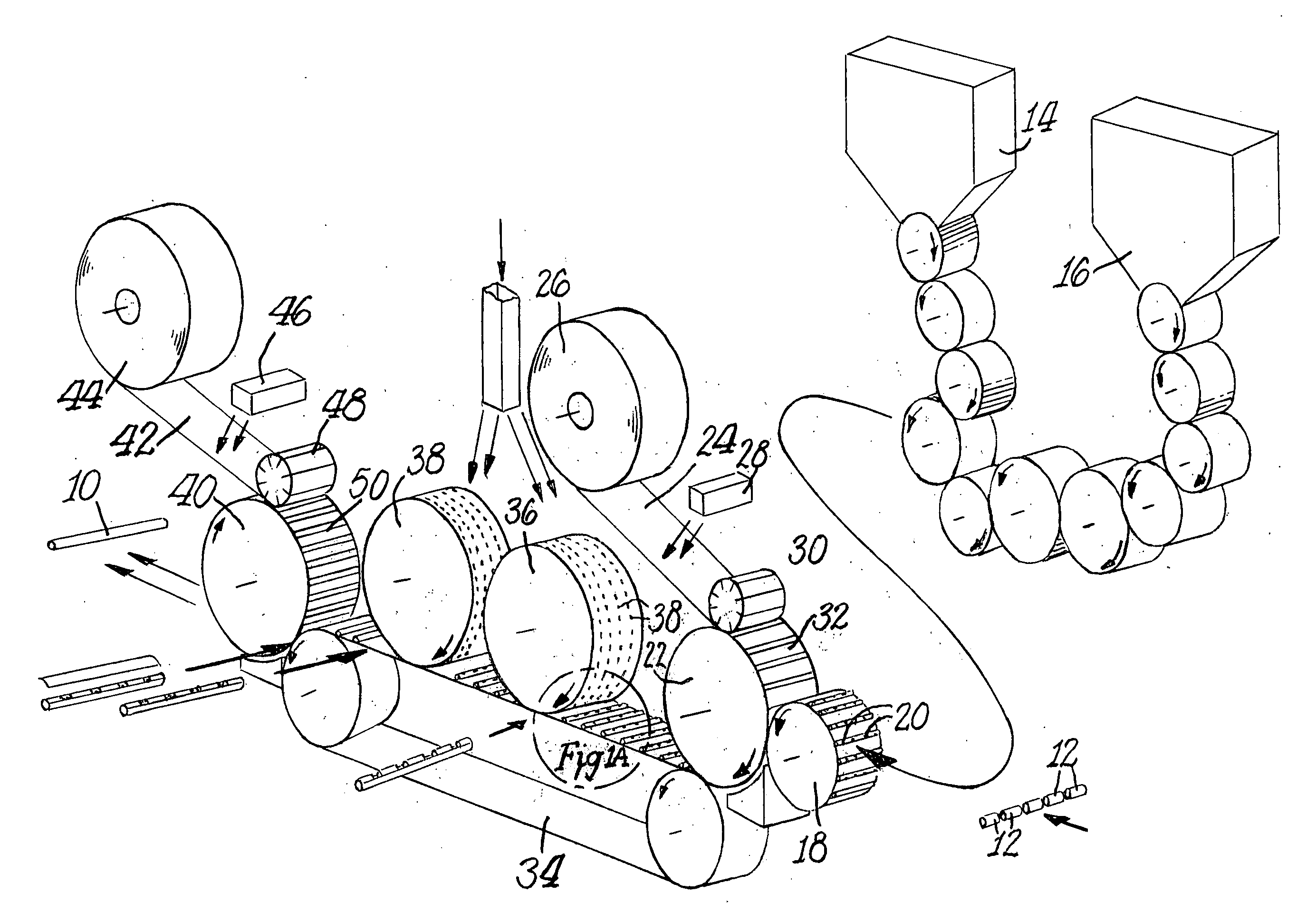
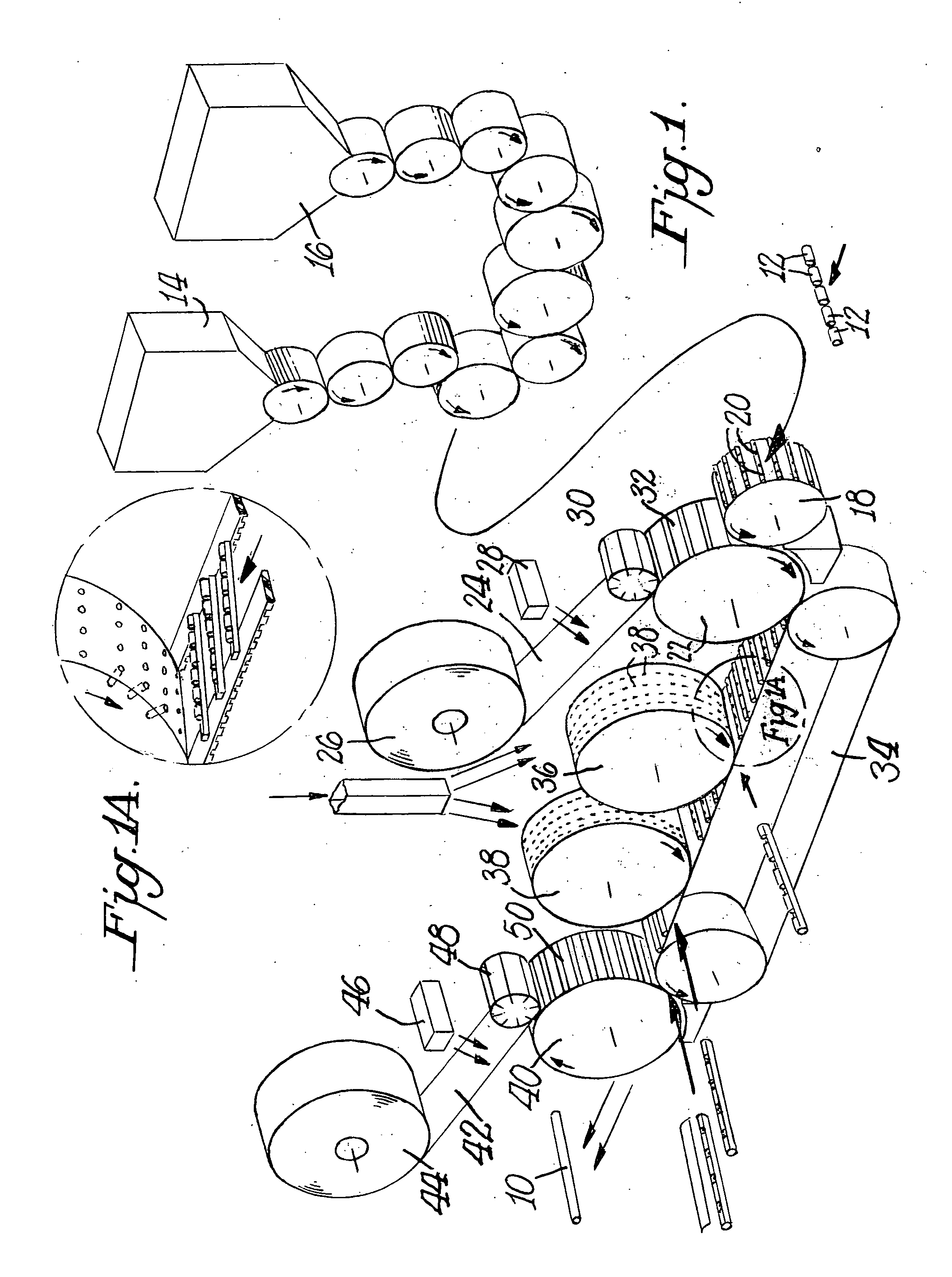
[0020] The filter component assembly of FIG. 1 shows one embodiment of the invention where filter components are processed to form finished combined filters. The method and apparatus of FIG. 1 will now be discussed in greater detail.

[0021] The filter assembly 10 is a combination of multiple segments 12 combined from base components that would enter the machine through the component hoppers 14, 16. The finished filter assembly could be a combination of only one or multiple unique base filter components 12. An example of this type of combining technology is the Hauni Mulfi -GC or a Dual Hopper Max such as described in commonly assigned U.S. Pat. No. 5,533,610, incorporated herein by reference.

[0022] Combining technology permits first filter rods to be prepared for the formation of combined filters. The filter rods are fed through a hopper system where they are cut, staggered, aligned, separated and otherwise processed to obtain components with predetermined characteristics including...


PUM


Abstract

Apparatus and method for forming cigarette filters comprise a single or multiple hopper system for forming filter components of single or multiple sizes. The filter components with spaces therebetween are partially wrapped and then conveyed to at least one media applying wheel where media is deposited into the spaces between the filter components. A cover cap is formed and placed over the partially wrapped filter components downstream of the media wheel to thereby completely wrap the filter components. Subsequently, the completely wrapped filter components are joined to tobacco rods with tipping paper.

Description

CROSS REFERENCE RELATED TO APPLICATION [0001] The present application claims the benefit of provisional application Ser. No. 60 / 640,531, filed Dec. 30, 2004, for all useful purposes, and the specification and drawings thereof are included herein by reference.BACKGROUND OF THE INVENTION [0002] Production lines for tobacco products often involve processing long rod shaped articles in a series fashion either continuously or through a series of drums to obtain a desired final result. Such a production line can comprise a plain cigarette processing apparatus (a cigarette rod maker or “maker”), such as by way of example a machine that is available from Hauni Machinenbau AG of Hamburg, Germany under the trade name PROTOS, a filter rod apparatus (“tipping machine”), such as by way of example a machine that is available from Hauni Machinenbau AG of Hamburg, Germany under the trade name MAX, and a packing machine.[0003] There are a number of patents related to the delivery of particles to fil...

Claims


Application Information

Patent Timeline
Patent Type & Authority Applications(United States)
IPC IPC(8): A24C5/47
CPCA24C5/475A24D3/0225A24D3/0287B65B1/36B65B19/00A24D3/02A24C5/47
Inventor BELCASTRO, MARC D.DUVEKOT, LOREN
Owner PHILIP MORRIS USA INC
Learn More