Perforated capsule filter

a filter and capsule technology, applied in the field of filters, can solve the problems of poor filtration of smokers, less than preferred, and carbon in smoking articles

Inactive Publication Date: 2006-07-20
GAUTHIER DARRELL
View PDF2 Cites 24 Cited by
  • Summary
  • Abstract
  • Description
  • Claims
  • Application Information

AI Technical Summary

Benefits of technology

[0011] More broadly, the present invention also provides a filter for any in-line application between a polluted source and a substantially pollutant-free product. The filter is the capsule of the present invention; namely, a perforated shell with media substantially air pocket free filtering media substantially filling the cavity formed by the shell. The capsule is placed at an effective point between the source and the product, and the media substantially filters the contaminant as the material flows through the perforated, media-filled capsule.

Problems solved by technology

While carbon plays an important role in the filtering process, the location of the carbon in the smoking article can lead to less than preferred results.
Unfortunately, because of limitations in filling the carbon cavity (without air pockets) through traditional gravitational fill methods air pockets are left in the carbon media.
Thus, current methods for using fibrous and carbon filter media do not make consistent or efficient use of the activated carbon media and also contribute to an inconsistent flavor as perceived by the smoker which causes the smoker to experience poor filtration (placing the smoker at greater risk, to experience different flavors, and to perceive inconsistent quality of the cigarette thereby resulting in reduced brand loyalty).
Another current deficiency in the use of activated charcoal is migration of the charcoal into the fibrous filter media.
Most notably, black discoloration of the fibrous filter media can occur as the carbon rests against the fibrous filter or migrates back towards the mouthpiece.
This can lead to another form of consumer complaint and dissatisfaction—perceived lower product quality.

Method used


Image

  • Perforated capsule filter
  • Perforated capsule filter
  • Perforated capsule filter

Examples


Embodiment Construction

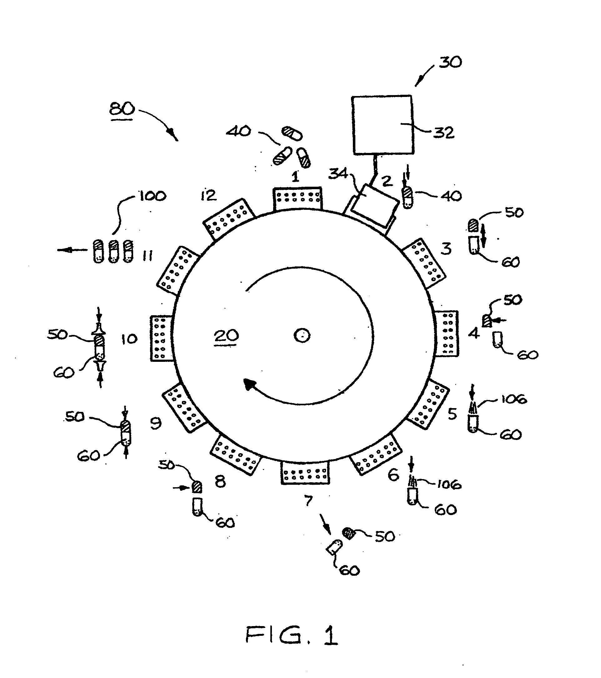
[0025] As illustrated in FIG. 1, one preferred method for forming the capsules of the present invention involves the modification of any standard hard capsule filling and closing machine 80, such as the Bosch GKF 400, GKF 700, GKF 1200, GKF 1500, GKF 2000, GKF 2500, GKF 3000, distributed by Bosch Group of TL Systems Corporation of Minneapolis, Minn. While any filling and closing machine may be used, as shown in FIG. 1, the machine 80 may include a turntable 20 which rotates among a plurality of process stations 1-12. One or more discrete process steps may be performed at each station 1-12. In the embodiment shown in FIG. 1, empty non-perforated capsules 40 are delivered to the turntable 20 at station 1, and the capsules 40 are straightened and aligned for subsequent processing. Next, the capsules 40 are passed to station 2 for perforation of the ends of the capsules 40 by laser 30. Laser 30 may include a control unit 32 and a remote head 34. Laser light is directed from the remote h...


PUM


Abstract

The present invention is a capsule that has a perforated outer shell that is substantially filled with a filtering media which has been pressurized to remove air pockets resulting in more effective and consistent filtration. The media may be activated carbon or other filtering media and may include other flavorants, aromatic substances, or a combination thereof. The present invention, thus, also provides an insert for a smoking article. The insert is the capsule of the present invention, namely, a perforated shell with media filling the cavity (without “air pockets”) formed by the shell. The capsule is placed within the smoking article at a point between the tobacco and the point of inhalation (the mouthpiece) such that, upon inhalation, the tobacco smoke is drawn completely and consistently through the media. Alternatively, the capsule may be integrated into a cigarette holder, pipe, or the like at a point in-line between the tobacco charge and the smoker.

Description

[0001] This is a continuation-in-part application of pending application Ser. No. 10 / 608650.FIELD OF THE INVENTION [0002] The present invention generally relates to a filter, and more particularly relates to an improved filter for smoking articles, such as cigarettes. BACKGROUND OF THE INVENTION [0003] Several filter designs exist for smoking articles, such as cigarettes, cigars, and similar articles. Such filters traditionally are formed with different types of filtering media to reduce or eliminate undesirable components from inhalation by the smoker. Fibrous filters, such as cellulose acetate or paper commonly are used as filter media for tobacco smoke. In addition, activated carbon is used in conjunction with the fibrous filter to absorb certain tobacco smoke combustion by-products. As used herein, “activated carbon” or “carbon” refers to charcoal that is treated to result in a highly porous, highly absorbent filter media. Thus, generally, a smoking article may contain a charge ...

Claims


Application Information

Patent Timeline
Patent Type & Authority Applications(United States)
IPC IPC(8): A24D3/06
CPCA24D3/061
Inventor GAUTHIER, DARRELL
Owner GAUTHIER DARRELL
Why Eureka
Try Eureka