Unsintered mesh sand control screen

a technology of unsintered mesh and control screen, which is applied in the direction of filtration separation, separation process, and well accessories, etc., can solve the problems of leakage path between the folds, product is extremely expensive to manufacture, and existing unsintered/non-diffusion bonded mesh layer products

Inactive Publication Date: 2006-07-20
PUROLATOR FACET INC
View PDF18 Cites 10 Cited by
  • Summary
  • Abstract
  • Description
  • Claims
  • Application Information

AI Technical Summary

Benefits of technology

[0003] In one aspect, a particle control screen assembly for a perforated pipe used in a well is provided. The particle control screen assembly includes a screen with a first end and a second end. The screen includes a first and a second unsintered woven mesh layer, each layer having a first longitudinal edge and a second longitudinal edge. The cylindrical screen includes openings sized to prevent passage of particulate material and a longitudinal metal weld adjacent the fi

Problems solved by technology

However, existing unsintered/non-diffusion bonded mesh layer products typically include a longitudinal seam joint that is created by folding

Method used


Image

  • Unsintered mesh sand control screen
  • Unsintered mesh sand control screen
  • Unsintered mesh sand control screen

Examples


Embodiment Construction

[0015] The invention is described with reference to the drawings. The relationship and functioning of the various elements of this invention are better understood by the following detailed description. However, the embodiments of this invention as described below are by way of example only, and the invention is not limited to the embodiments illustrated in the drawings.

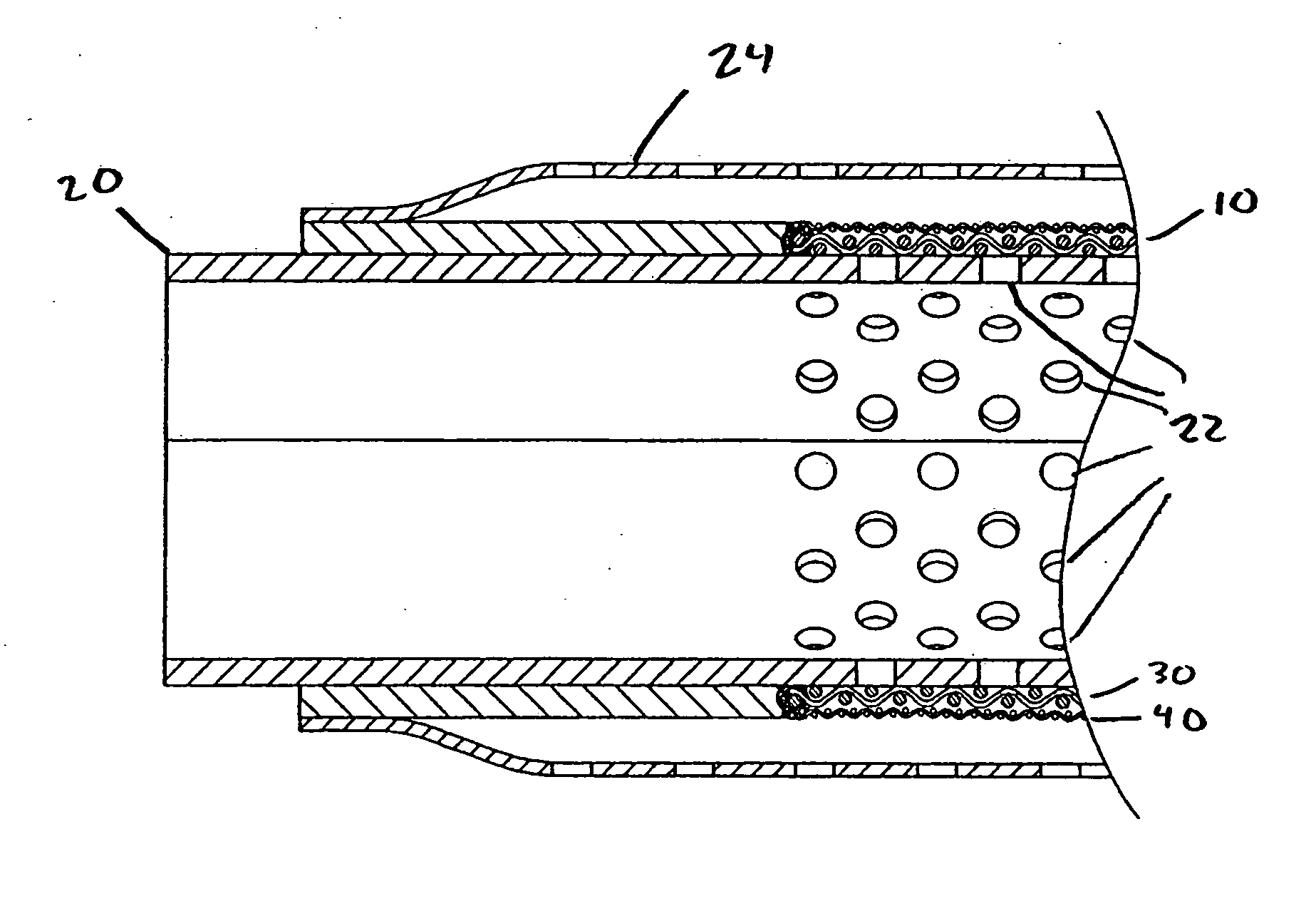
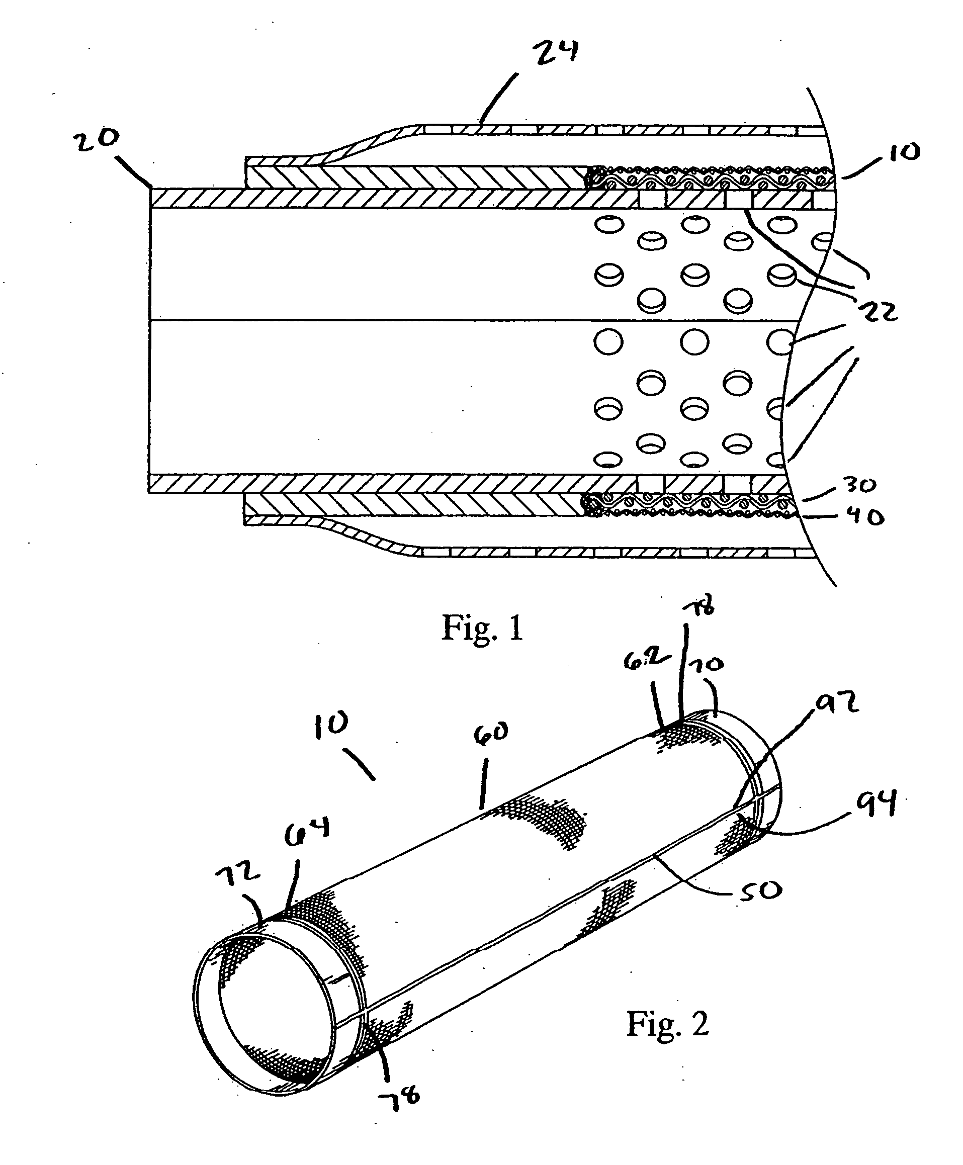
[0016] Referring to FIG. 1, an embodiment of a particle control screen assembly 10 is illustrated as being incorporated into a sand or other particle filter system. The particle control screen assembly 10 is mounted on a base pipe 20 that is disposed, for example, in a wellbore. To draw in petroleum or natural gas from the wellbore, a portion of the base pipe 20 is perforated with holes 22. To prevent sand and other particles from being drawn into the base pipe 20 through such holes 22, the perforated portion of the base pipe 20 is covered by the particle control screen assembly 10.

[0017] As shown in FIGS. 1 and 2, ...


PUM

PropertyMeasurementUnit
Lengthaaaaaaaaaa
Lengthaaaaaaaaaa
Lengthaaaaaaaaaa

Abstract

A particle control screen assembly for a perforated pipe used in a well. The particle control screen assembly includes a screen with a first end and a second end. The screen includes a first and a second unsintered woven mesh layer, each layer having a first longitudinal edge and a second longitudinal edge. The cylindrical screen also includes openings sized to prevent passage of particulate material and a longitudinal metal weld adjacent the first and second longitudinal edges of the first and second unsintered woven mesh layers. The longitudinal metal weld secures the edges of the unsintered woven mesh layers together. The particle control screen assembly also includes a weld-compatible metal structure adjacent the first end of the cylindrical screen. A circumferential metal weld between the cylindrical screen and the metal structure bonds a portion of the metal structure and a portion of the cylindrical screen.

Description

BACKGROUND [0001] Particle control screen assemblies have been used for perforated pipes used in a well. The particle control screen assembly typically includes at least one outer cylindrical perforated plate and at least one inner fine mesh control screen contained therein. For example, arrangements of particle control screen assemblies for a perforated pipe used in a well are disclosed in U.S. Pat. Nos. 5,782,299, 5,899,271, and 5,937,944, all to Simone et al., and commonly owned by the present assignee of the instant patent application. [0002] In this field, it is desirable to minimize leakage of sand or other particulate into the perforated pipe. There are several sand control products that use an unsintered / non-diffusion bonded mesh layer for the filter medium and subsequent drainage layers. However, existing unsintered / non-diffusion bonded mesh layer products typically include a longitudinal seam joint that is created by folding or crimping. This longitudinal seam joint create...

Claims


Application Information

Patent Timeline
IPC IPC(8): E03B3/18
CPCB01D29/111B01D2201/188E03B3/18E21B43/084B01D29/15
Inventor HOPKINS, SAM A.ALT, BRADY S.
Owner PUROLATOR FACET INC
Why Eureka
Try Eureka