Tape printing apparatus

a printing apparatus and tape technology, applied in printing, typewriters, etc., can solve the problems of reducing the number of batteries and unable to effectively utilize space, and achieve the effect of effective space utilization

Inactive Publication Date: 2006-07-20
SEIKO EPSON CORP +1
View PDF8 Cites 2 Cited by
  • Summary
  • Abstract
  • Description
  • Claims
  • Application Information

AI Technical Summary

Benefits of technology

[0007] It is an advantage of the invention to provide a tape printing apparatus having a cartridge mounting unit, a battery accommodating unit, and a finger-hooking groove unit arranged therein with effective space utilization.
[0008] According to an aspect of the invention, there is provided a tape printing apparatus in which a cartridge mounting unit where a tape cartridge having a print tape accommodated therein is detachably mounted, a battery accommodating unit where a plurality of batteries serving as power supply are accommodated, and a finger-hooking groove unit for removing the batteries from the battery accommodating unit are formed with a groove on a surface of an apparatus casing. In the tape printing apparatus, the finger-hooking groove unit and the cartridge mounting unit are disposed such that they are overlapped with each other in the plane of the surface.
[0009] According to this configuration, a space for the finger-hooking groove unit other than the cartridge mounting unit and the battery accommodating unit can be made small since the finger-hooking groove unit is disposed so as to overlap with the cartridge mounting unit. Accordingly, the overlapped disposition makes it possible to set the battery accommodating unit that much nearer to the cartridge mounting unit, which in turn makes it possible to prevent the apparatus from growing in size even if the battery accommodating unit requires more space.
[0010] In this case, it is preferable that an auxiliary line representing the contour of the tape cartridge be provided at the groove bottom of the finger-hooking groove unit.
[0011] According to this configuration, the user is prevented from inserting the tape cartridge in the opposite direction since the auxiliary line indicates the contour of the tape cartridge.
[0012] In this case, it is preferable that the battery accommodating unit have a plurality of individual accommodating sections where the plurality of batteries are accommodated in a two-tiered system and arranged side by side, and the neighboring individual accommodating sections be disposed such that they are mutually shifted in the longitudinal direction of the batteries.

Problems solved by technology

However, effective space utilization is not possible with the tape printing apparatus of this type since the finger-hooking groove unit is formed independently with a groove, which prevents miniaturization of and reduces the number of accommodated batteries.

Method used


Image

  • Tape printing apparatus
  • Tape printing apparatus
  • Tape printing apparatus

Examples


Embodiment Construction

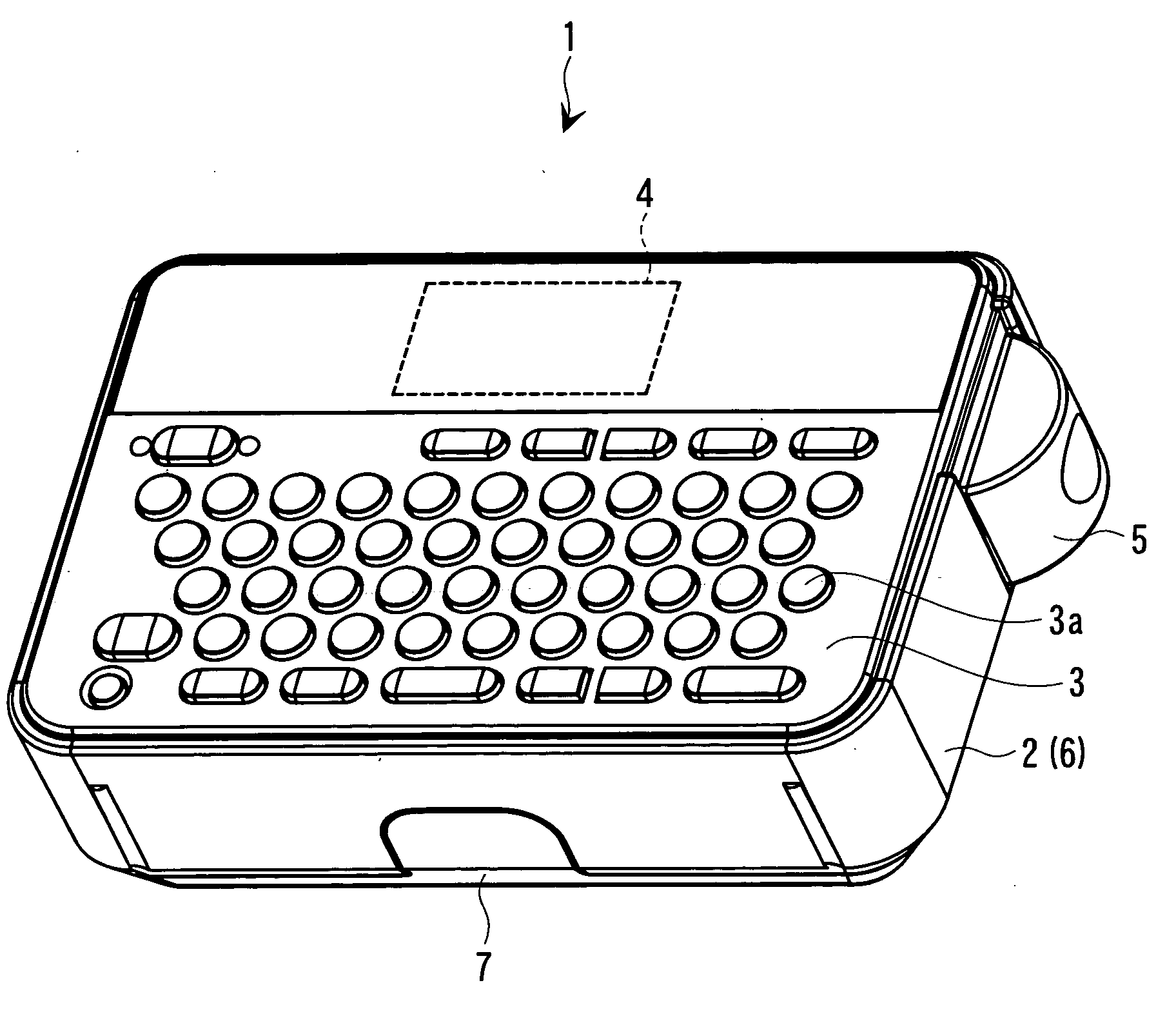
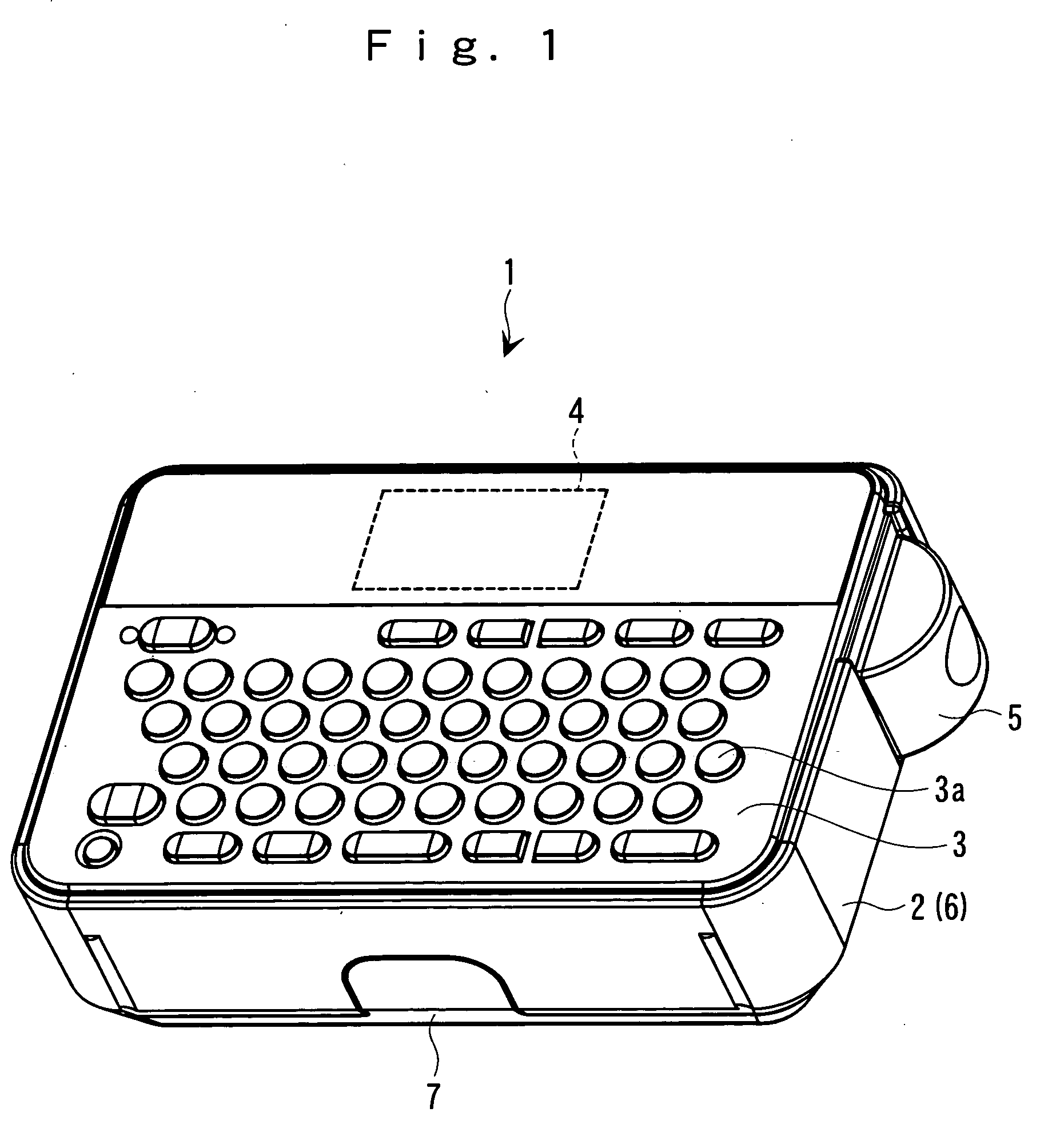
[0020] Hereinafter, description will be made about a tape printing apparatus of the invention referring to the accompanying drawings. This tape printing apparatus is of a portable type mainly using batteries as power supply and performs a printing operation on a print tape which is fed out from a tape cartridge mounted on the back surface side, so as to form a strip label.

[0021]FIG. 1 is an external perspective view of the tape printing apparatus 1. As shown in FIG. 1, the tape printing apparatus 1 has a substantially rectangular box-shaped outer hull formed by an apparatus casing 2. On the front side of the apparatus casing 2, a keyboard 3 including various input keys 3a and complying with the JIS (Japanese Industrial Standards) and a display 4 are disposed on the near and far sides, respectively. On the right side surface of the apparatus casing 2, a semi-circular cutter operating lever 5 is disposed so that the print tape T is manually cut.

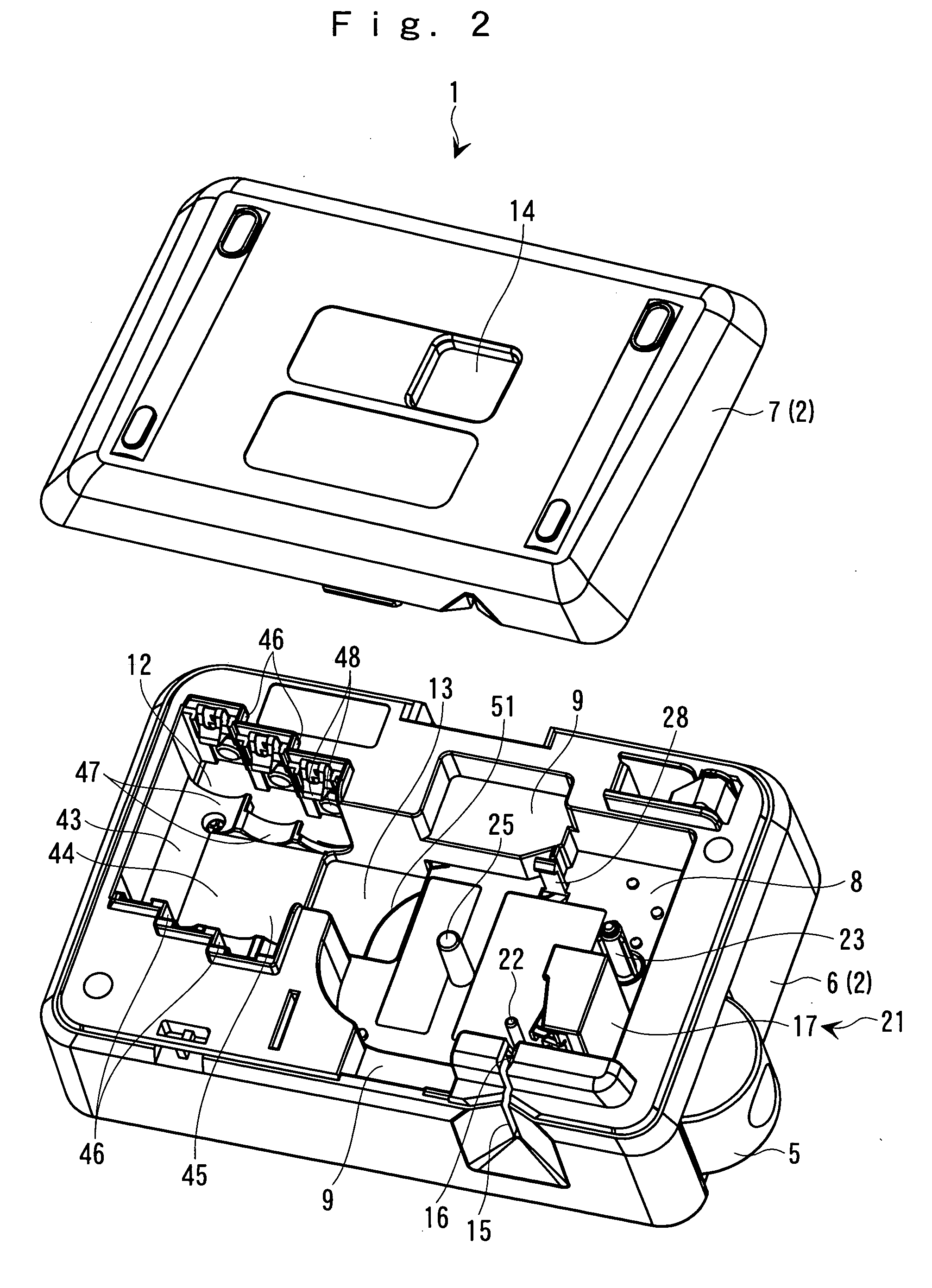
[0022]FIGS. 2 and 3 are external persp...


PUM


Abstract

There is provided a tape printing apparatus in which a cartridge mounting unit where a tape cartridge having a print tape accommodated therein is detachably mounted, a battery accommodating unit where a plurality of batteries serving as power supply are accommodated, and a finger-hooking groove unit for removing the batteries from the battery accommodating unit are formed with a groove on a surface of an apparatus casing, wherein the finger-hooking groove unit and the cartridge mounting unit are disposed such that they are overlapped with each other in the plane of the surface.

Description

[0001] The entire disclosure of Japanese Patent Application No. 2005-007789, filed Jan. 14, 2005, is expressly incorporated by reference herein. BACKGROUND [0002] 1. Technical Field [0003] The present invention relates to a portable tape printing apparatus which performs a printing operation using batteries as power supply. [0004] 2. Related Art [0005] A tape printing apparatus used hitherto is of a type which the user can operate in a hand-held state. JP-A-2004-195895 is an example of related art. In this tape printing apparatus, a cartridge mounting unit where a cartridge including a print tape is mounted and a battery accommodating unit where batteries are accommodated are formed on the back surface of an apparatus casing such that they are arranged in the longitudinal direction thereof. Furthermore, at the lateral part of the battery accommodating unit, a finger-hooking groove unit communicating therewith is formed. The battery accommodating unit has a total of four batteries ar...

Claims


Application Information

Patent Timeline
Patent Type & Authority Applications(United States)
IPC IPC(8): B41J3/36
CPCB41J3/4075
Inventor SODEYAMA, HIDEOTANABE, KENICHI
Owner SEIKO EPSON CORP
Why Eureka
Try Eureka