High pressure container

a container and high-pressure technology, applied in the direction of container discharging methods, vessel construction details, transportation and packaging, etc., can solve the problems of reducing the amount of cabin space or luggage space, and unable to efficiently utilize the space in the vehicle, so as to achieve excellent advantageous effect, facilitate efficient vehicle space utilization, and excellent advantageous

Inactive Publication Date: 2019-10-03
TOYOTA JIDOSHA KK
View PDF8 Cites 2 Cited by
  • Summary
  • Abstract
  • Description
  • Claims
  • Application Information

AI Technical Summary

Benefits of technology

[0018]According to the sixth aspect, the interiors of the adjacent container bodies of the high pressure container are placed in communication with each other by the communication flow path. This thereby enables the stress within the adjacent container bodies of the high pressure container to be made uniform, enabling a concentration of stress on the reinforcement layers at a portion of the high pressure container to be reduced or prevented.
[0019]The high pressure container according to the first aspect exhibits the excellent advantageous effect of enabling efficient vehicle space utilization.
[0020]The high pressure containers according to the second aspect, the third aspect, the fifth aspect, the sixth aspect, and the seventh aspect exhibit the excellent advantageous effect of enabling the amount of internally stored high pressure fluid to be increased.
[0021]The high pressure containers of the fourth aspect and the eighth aspect exhibit the excellent advantageous effect of enabling productivity to be improved.

Problems solved by technology

However, this high pressure hydrogen tank has a large barrel shape, which could reduce the amount of cabin space or the amount of luggage space in a vehicle to which the high pressure hydrogen tank is installed.
Namely, efficient utilization of space in the vehicle might not be possible.
However, providing plural tanks necessitates a reinforcement layer for each tank, and it is possible that securing the space equivalent to the reinforcement layers might impinge on the cabin space or luggage space.

Method used


Image

  • High pressure container
  • High pressure container
  • High pressure container

Examples


Embodiment Construction

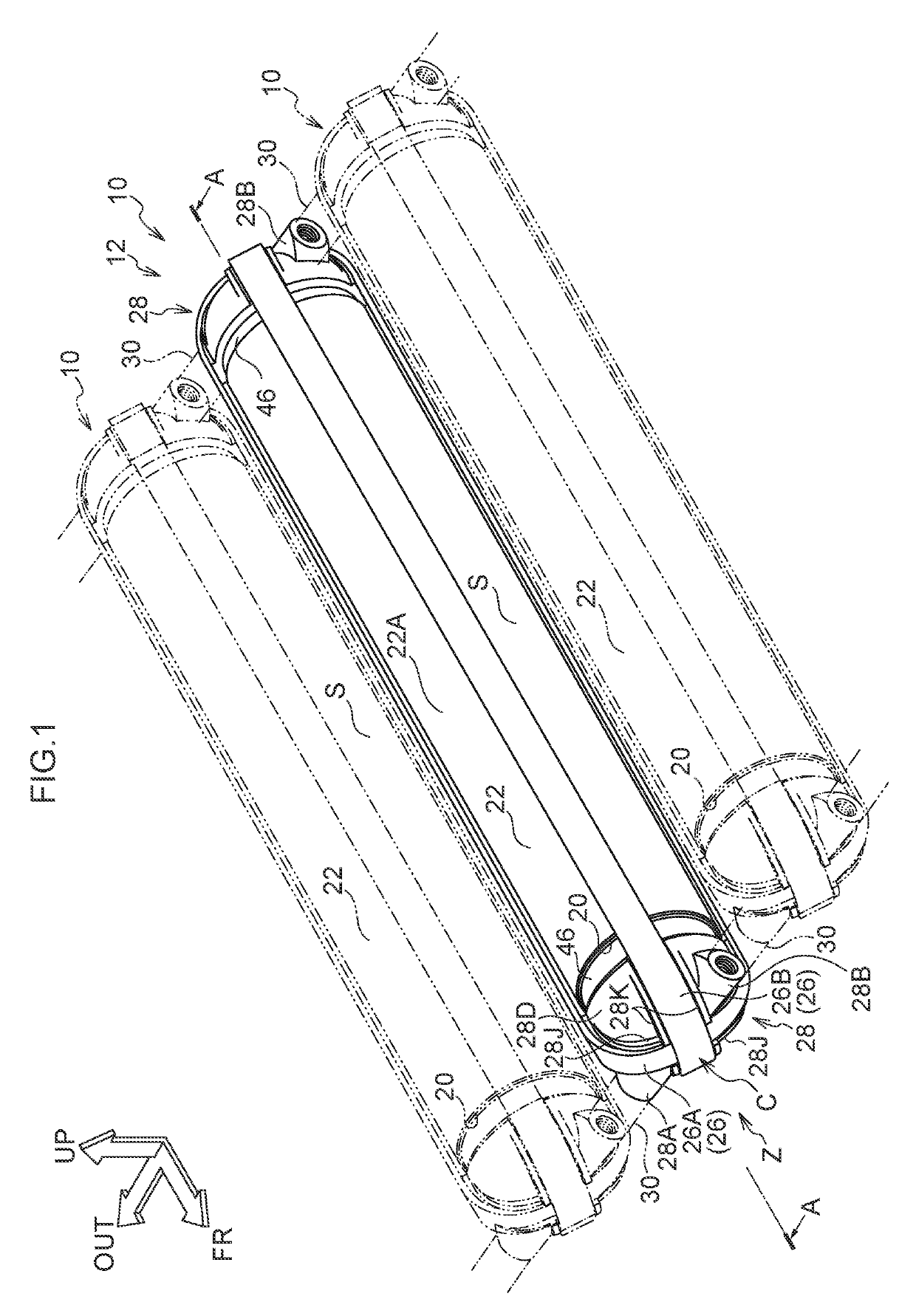
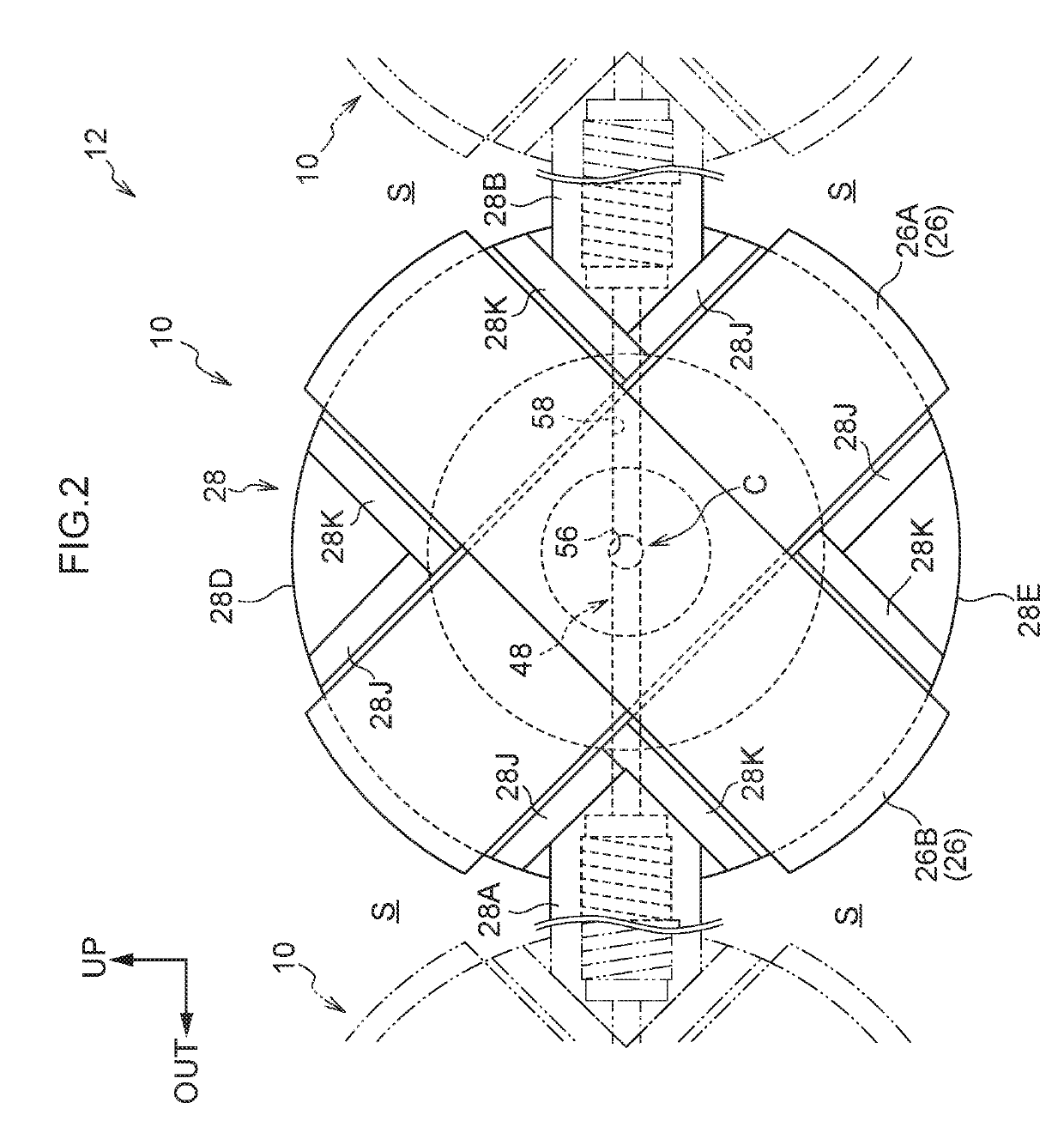
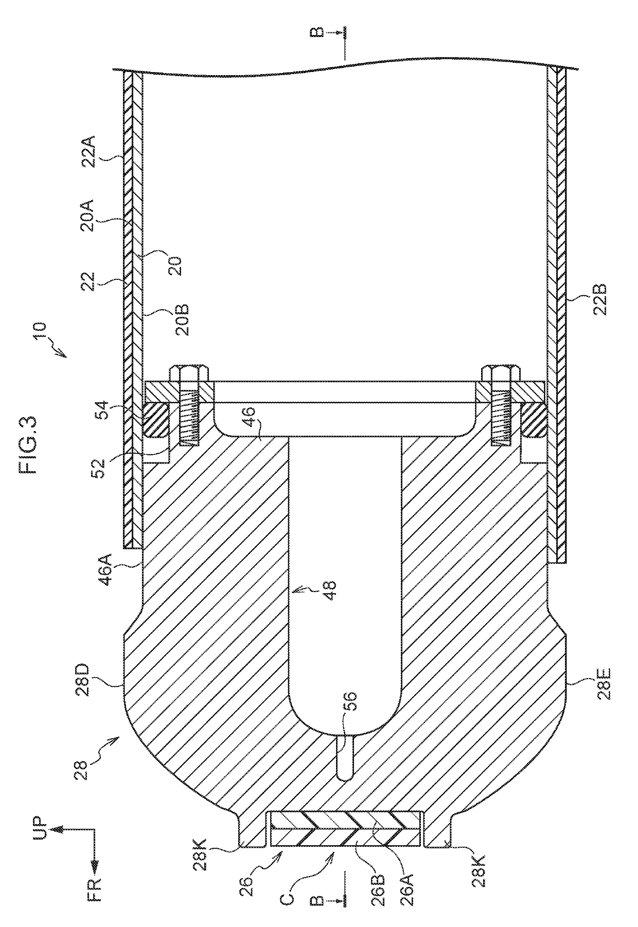
[0028]Explanation follows regarding an exemplary embodiment of a high pressure container 10 according to the present disclosure, with reference to FIG. 1 to FIG. 5. In the drawings, the arrow FR indicates a vehicle front-rear direction front side, the arrow OUT indicates a vehicle width direction outer side, and the arrow UP indicates a vehicle vertical direction upper side.

[0029]As illustrated in FIG. 1, a tank module 12 is configured by combining plural of the high pressure containers 10. Specifically, each high pressure container 10 is formed in a substantially circular column shape with its axial direction (length direction) running along the vehicle front-rear direction. Plural similarly configured high pressure containers 10 are arranged adjacent to each other along the vehicle width direction (a radial direction of the high pressure containers 10). The tank module 12 is, for example, disposed at a vehicle lower side of a floor panel (not illustrated in the drawings) of a fuel...


PUM

PropertyMeasurementUnit
pressureaaaaaaaaaa
diameteraaaaaaaaaa
widthaaaaaaaaaa

Abstract

Reinforcement layers are each formed in a belt shape set with a smaller width than a diameter dimension of a container body. Each reinforcement layer has its length direction along an axial direction of the container body and spans between one axial direction side end and another axial direction side end of the container body, including at caps. Moreover, the reinforcement layers span across the caps and the container body at locations other than maximum diameter portions, these being locations where the diameter dimensions of the cap and the container body are greatest in a direction orthogonal to a direction of adjacency of the container body with other container bodies as viewed along the axial direction.

Description

CROSS-REFERENCE TO RELATED APPLICATION[0001]This application is based on and claims priority under 35 USC 119 from Japanese Patent Application No. 2018-065253 filed on Mar. 29, 2018, the disclosure of which is incorporated by reference herein.BACKGROUNDTechnical Field[0002]The present disclosure relates to a high pressure container.Related Art[0003]Japanese Patent Application Laid-Open (JP-A) No. 2002-188794 discloses an example of a high pressure hydrogen tank. This high pressure hydrogen tank is configured including a barrel-shaped liner and a reinforcement layer configured by fiber reinforced plastic wrapped around the liner. This configuration raises the rigidity of the liner, enabling hydrogen to be stored at high pressure therein.[0004]However, this high pressure hydrogen tank has a large barrel shape, which could reduce the amount of cabin space or the amount of luggage space in a vehicle to which the high pressure hydrogen tank is installed. Namely, efficient utilization of ...

Claims


Application Information

Patent Timeline
Patent Type & Authority Applications(United States)
IPC IPC(8): F17C1/02F17C1/00F17C1/14
CPCF17C2205/0308F17C1/02F17C1/005F17C2201/0109F17C1/14F17C2203/0604F17C1/06F17C13/002F17C13/04F17C13/06F17C2201/0104F17C2203/012F17C2205/0311F17C2201/058F17C2201/056F17C1/00F17C2201/035F17C2205/0134F17C2203/0609F17C2205/0305F17C2221/012F17C2223/0123F17C2223/036F17C2203/0663F17C2260/018F17C2205/0146F17C2270/0178Y02E60/32
Inventor SAWAI, OSAMU
Owner TOYOTA JIDOSHA KK
Why Eureka
Try Eureka