
Apparatus and method for aligning a substantial point source of light with a reflector feature

a technology of reflectors and apparatuses, which is applied in the direction of lighting and heating apparatus, fixed installation, lighting support devices, etc., can solve the problems of affecting the quality and intensity of beams, improper lighting of lamp bulbs, and beam aberration, so as to improve the design of switch elements, improve the effect of light intensity and absorb stress

Active Publication Date: 2006-07-20
MAG INSTR INC
View PDF99 Cites 1 Cited by
  • Summary
  • Abstract
  • Description
  • Claims
  • Application Information

AI Technical Summary

Benefits of technology

"The present invention provides a combination for positioning a substantial point source of light with a reflector, which can be used in a flashlight. The combination includes a reflector, a lamp bulb, a movable lamp bulb holder, and an actuating member. The actuating member moves the point source of light relative to the reflector axis. The combination also includes a lock mechanism to maintain the position of the point source of light after it has been aligned with the reflector axis. The flashlight may also include an adjustable focusing means to vary the position of the point source of light with respect to the focal point in a direction parallel to the reflector axis. The flashlight also includes an improved switch design to protect the battery and other flashlight components from damage. The method of aligning the point source of light with the reflector axis is also provided. The technical effects of the invention include improved positioning of the point source of light and better protection of the flashlight components."

Problems solved by technology

The light pattern formed by the beam emanating from such light devices is frequently asymmetrical or elongated in shape which adversely impacts on the quality and intensity of the beam.
These beam aberrations generally result from the fact that the flashlight lamp bulb is not properly aligned with the reflector of the assembled flashlight.
Due to manufacturing and assembly operations and tolerances, however, after manufacture of the lighting device is fully completed, the lamp is typically misaligned with the reflector, resulting in degraded performance.
Although this patent's attempt to avoid a misalignment of the lamp bulb to the reflector is an improvement over the prior art, simply aligning the lamp bulb relative to the reflector does not ensure that aberrations in the projected light beam will be eliminated.
Manually maneuvering the lamp bulb to address the misalignment problem is impractical.
During operation, the temperature of an illuminating lamp bulb is too high to allow for manual adjustment.
While such switches have generally worked well for flashlights that employ smaller batteries of the AA or AAA type, known designs are less suitable for flashlights that employ larger battery sizes, such as C or D size batteries.
One reason such designs are not well suited for flashlights employing larger batteries is that the positive electrode of the battery closest to the head end of the flashlight is urged against a conductor mounted flush against the bottom of the switch.
As a result, the battery or batteries or the conductor may become damaged in the event that the flashlight is shaken or dropped.
The problem also becomes more acute as the number of batteries connected in series increases due to the added weight, and hence momentum, of the multiple batteries.
While variable focus flashlights have also employed switches that are adapted to open and close in response to the axial movement of the head assembly, such flashlights have generally been limited to flashlights employing AA and AAA batteries for a variety of reasons, including some of those described above.

Method used


Image

  • Apparatus and method for aligning a substantial point source of light with a reflector feature
  • Apparatus and method for aligning a substantial point source of light with a reflector feature
  • Apparatus and method for aligning a substantial point source of light with a reflector feature

Examples


Embodiment Construction

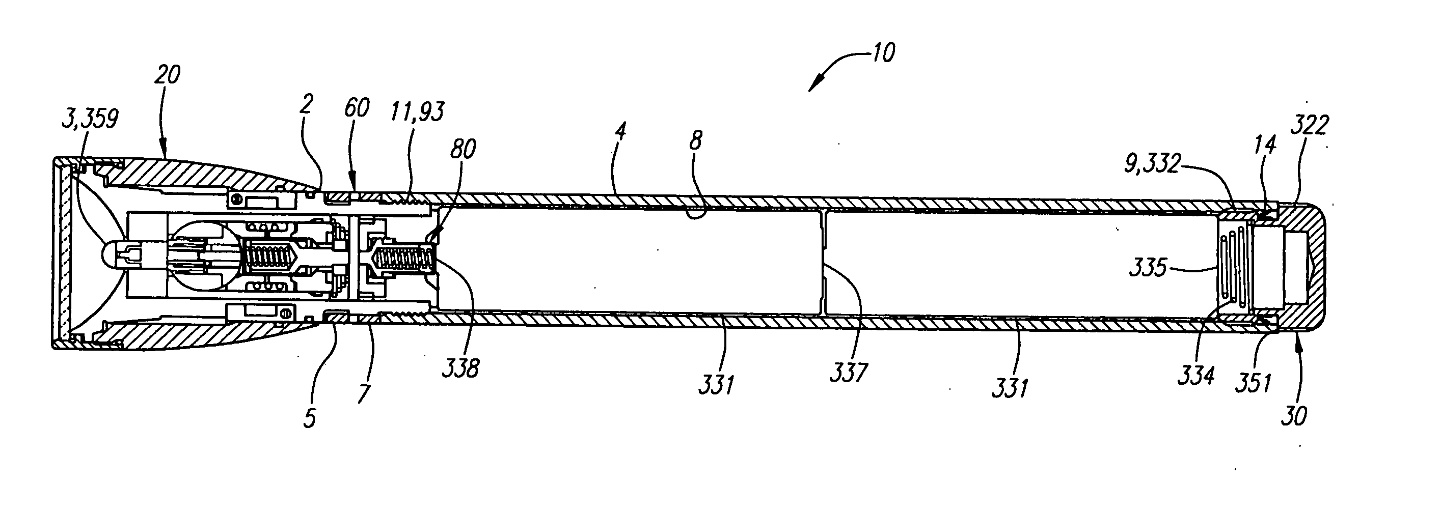
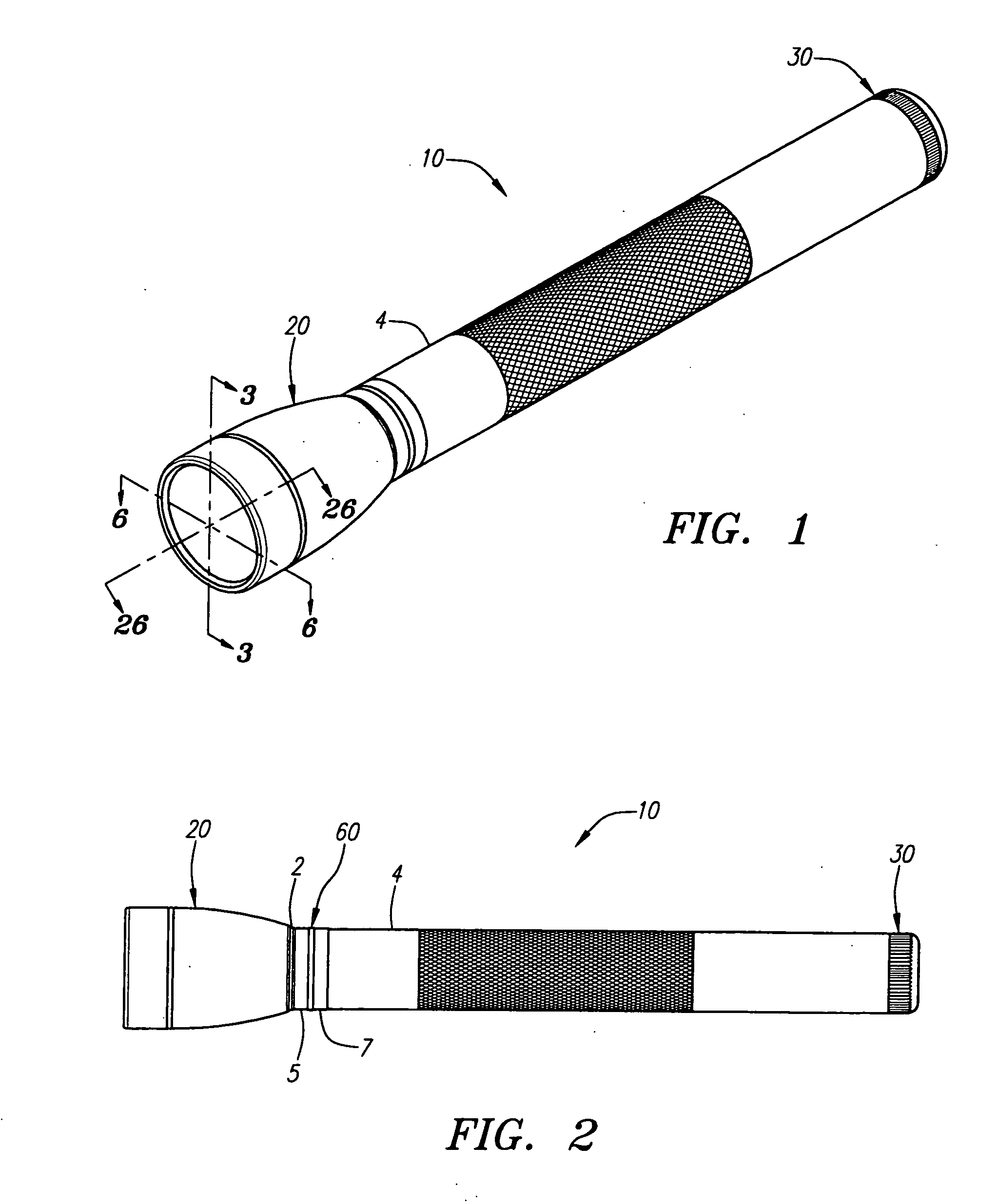
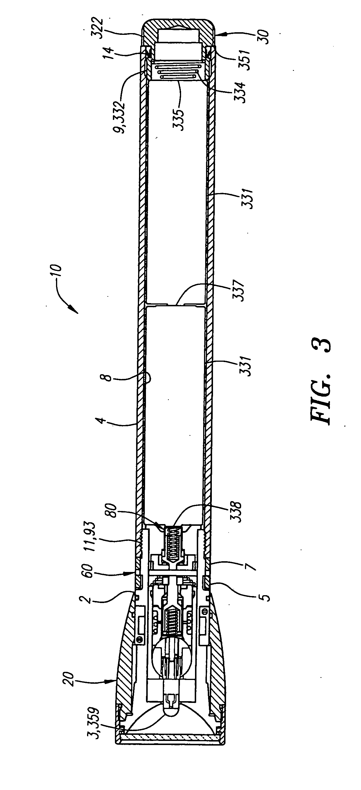
[0076] Embodiments of the present invention will now be described with reference to the drawings. To facilitate description, any reference numeral representing an element in one figure will represent the same element in any other figure. Further, in the description of the present invention that is to follow, upper, front, forward or forward facing side of a component shall generally mean the orientation or the side of the component facing the direction toward the front end of the flashlight where the light source is disposed. Similarly, lower, aft, back, rearward or rearward facing side of a component shall generally mean the orientation or the side of the component facing the direction toward the rear of the flashlight where the tail cap is located.

[0077] Referring to FIGS. 1 and 28, lighting devices in the form of flashlights 10 and 300, each an embodiment of the present invention, are illustrated in perspective, respectively. Each of flashlight 10 and flashlight 300 incorporates...


PUM


Abstract

A combination for use in aligning a substantial point source of light with respect to an axis of a reflector is provided. The combination includes a reflector, a lamp bulb having a substantial point source of light, and a movable lamp bulb holder. The movable holder may be moved using an actuating member. The reflector has a first open end for emitting a light beam, a second end and an axis extending between the first and second reflector ends. The lamp bulb is secured to the movable holder and is disposed about the second end of the reflector. The actuating member is operatively coupled to the movable holder at an actuation interface for moving the substantial point source of light relative to the axis of the reflector and aligning the substantial point source of light with the reflector axis and the focal point of the reflector. Flashlights employing the combination are provided.

Description

[0001] This is a divisional application of co-pending application Ser. No. 10 / 802,265, filed Mar. 16, 2004, which is incorporated herein by reference.BACKGROUND [0002] The field of the present invention relates to hand held or portable lighting devices, including flashlights and flashlight components. [0003] Various hand held or portable lighting devices, including flashlight designs, are known in the art. Flashlights typically include one or more dry cell batteries having positive and negative electrodes. In certain designs, the batteries are arranged in series in a battery compartment of a barrel or housing that can be used to hold the flashlight. An electrical circuit is frequently established from a battery electrode through conductive means which are in electrical contact with an electrode of a lamp bulb. After passing through the lamp bulb, the electric circuit continues through a second electrode of the lamp bulb in electrical contact with conductive means, which in turn are ...

Claims


Application Information

Patent Timeline
Patent Type & Authority Applications(United States)
IPC IPC(8): F21L4/00F21L4/02F21L4/04F21V15/01F21V19/02F21V23/04F21V31/03
CPCF21L4/005F21L4/027F21V15/01F21V19/02F21V19/047F21V23/0414F21V31/03F21Y2101/02F21Y2101/00F21L4/00F21L4/04
Inventor MAGLICA, ANTHONY
Owner MAG INSTR INC
Learn More