Heating system for pet-preforms

a heating system and pet-shaped technology, applied in the field of heating systems for pet-shaped forms, can solve the problem of only having limited options for adapting the heating process, and achieve the effects of improving the heating of the bottom, reducing the radiative energy absorbed, and high resolution

Inactive Publication Date: 2016-03-17
KONINKLJIJKE PHILIPS NV
View PDF0 Cites 2 Cited by
  • Summary
  • Abstract
  • Description
  • Claims
  • Application Information

AI Technical Summary

Benefits of technology

[0015]The reflecting device may alternatively be integrated within the holding device. The reflecting device may be in this case a specular reflecting surface and / or a diffuse reflecting surface within the preform redirecting light to the bottom of a preform. The reflecting surface may be placed on a post extending from the holding device within the preform. The reflecting surface can in this case be nearer to the surface and thus the bottom of the preform. The post holding the reflecting surface should itself be transparent or reflective, in order to minimize the radiative energy absorbed by it. The heating of the bottom may even be improved by arranging the shape of the reflecting surface in a way that the heating of the bottom of the preform is adapted to the intended shape of the bottle, especially the intended shape of the bottom of the bottle after the heating and bottle blowing process.
[0016]In the case the lighting equipment comprises at least one light source being arranged underneath of the holding device in order to directly heat the bottom of the preform it may be advantageous that the light source comprises at least a first and a second laser. The first laser is arranged to heat a first part of the bottom of the preform and the second laser is arranged to heat a second part of the bottom of the preform. Using more than one laser may have the advantage that the bottom of the preform can be heated in a more defined way. The heating system or to be more precise the driver driving the light source(s) of the lighting equipment may even be arranged to control the intensity of the laser light emitted by the first laser independently from the laser light emitted by the second laser. Lasers or laser arrays which can be controlled independently from each other may be used to define the heating profile of the bottom of the preform nearly point by point. Especially laser arrays comprising a multitude of small VCSEL which can be controlled independently may enable a laser light pattern with a high resolution. Alternatively or in addition groups of VCSEL or VCSEL arrays may be controlled in parallel such that different heating zones are enabled. A combination of VCSEL being commonly controlled and individually controlled may be advantageous if the shape of final PET-bottle comprises uniform areas (e.g. cylindrical parts of the final PET-bottle) and areas with, for example, irregular shapes. A temperature profile may be “imprinted” into the bottom of the preform, thus allowing for wider options for the design of the final PET-bottle bottom. The lasers or laser arrays may be coupled to sensor devices detecting the presence of a preform above the lasers. Especially cameras may be used to detect the position in a precise way such that the control of each laser or each sub array can be adapted to the positions of the preforms. Cameras being sensitive in the IR part of the spectrum may even be used to detect the heating profile of the bottom of the preform in order to control the lasers accordingly.
[0017]Heating systems in which the lighting equipment comprises at least one light source being integrated in the holding device may have the advantage that the bottom of the preform can be directly heated in an easy way. The relative position of the preform and the light source or light sources doesn't change. Especially light sources emitting directed light like lasers may be advantageous. A fixed heating profile can be provided which may only change over time in order to adapt the heat supply to the preform in order to enable the intendended heating profile of the preform.

Problems solved by technology

The described method provides only limited possibilities to adapt the heating process to the final form of the processed preform.

Method used


Image

  • Heating system for pet-preforms
  • Heating system for pet-preforms
  • Heating system for pet-preforms

Examples


second embodiment

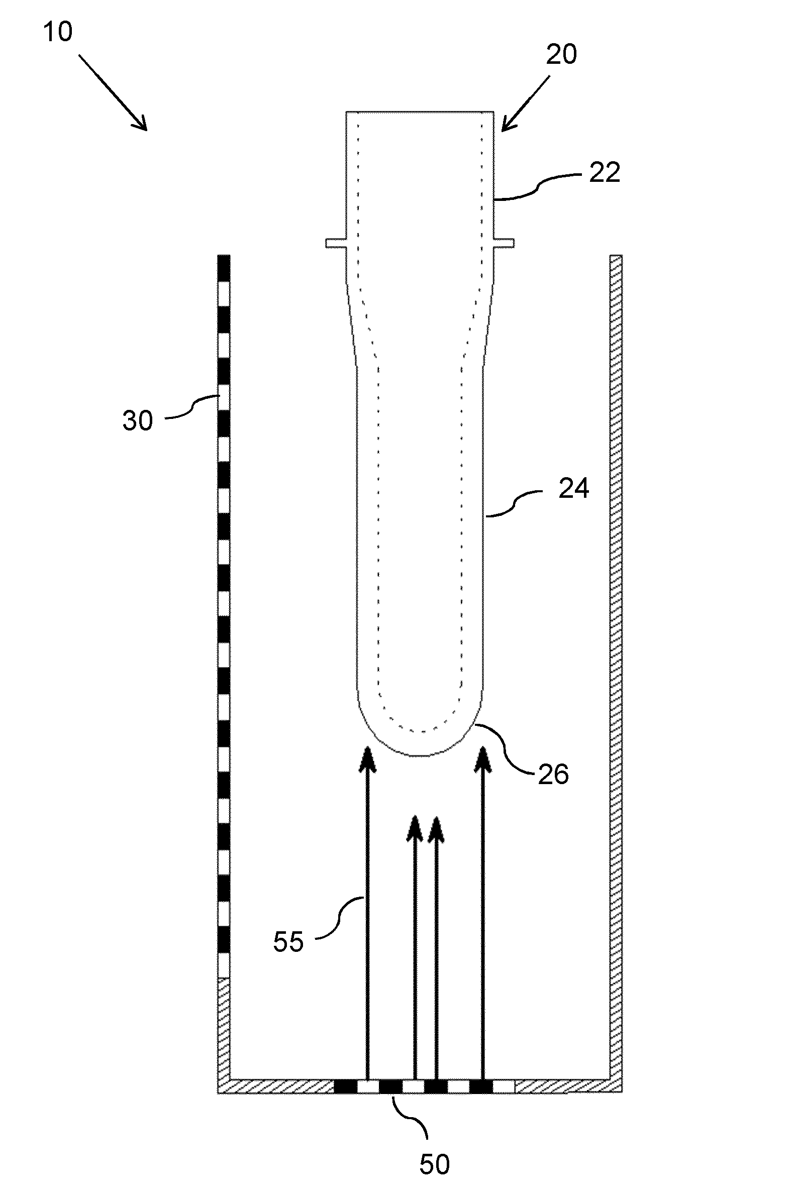
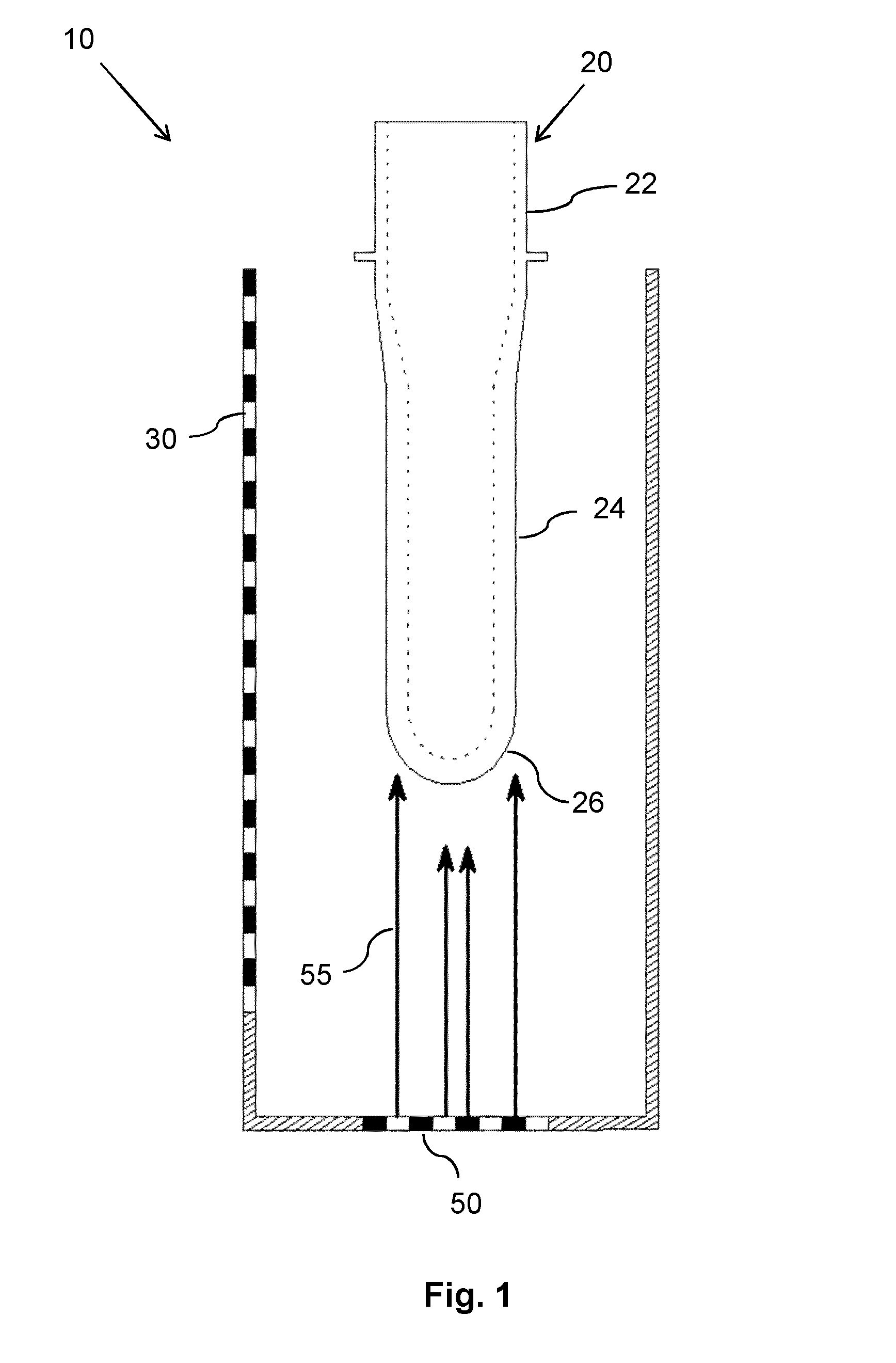
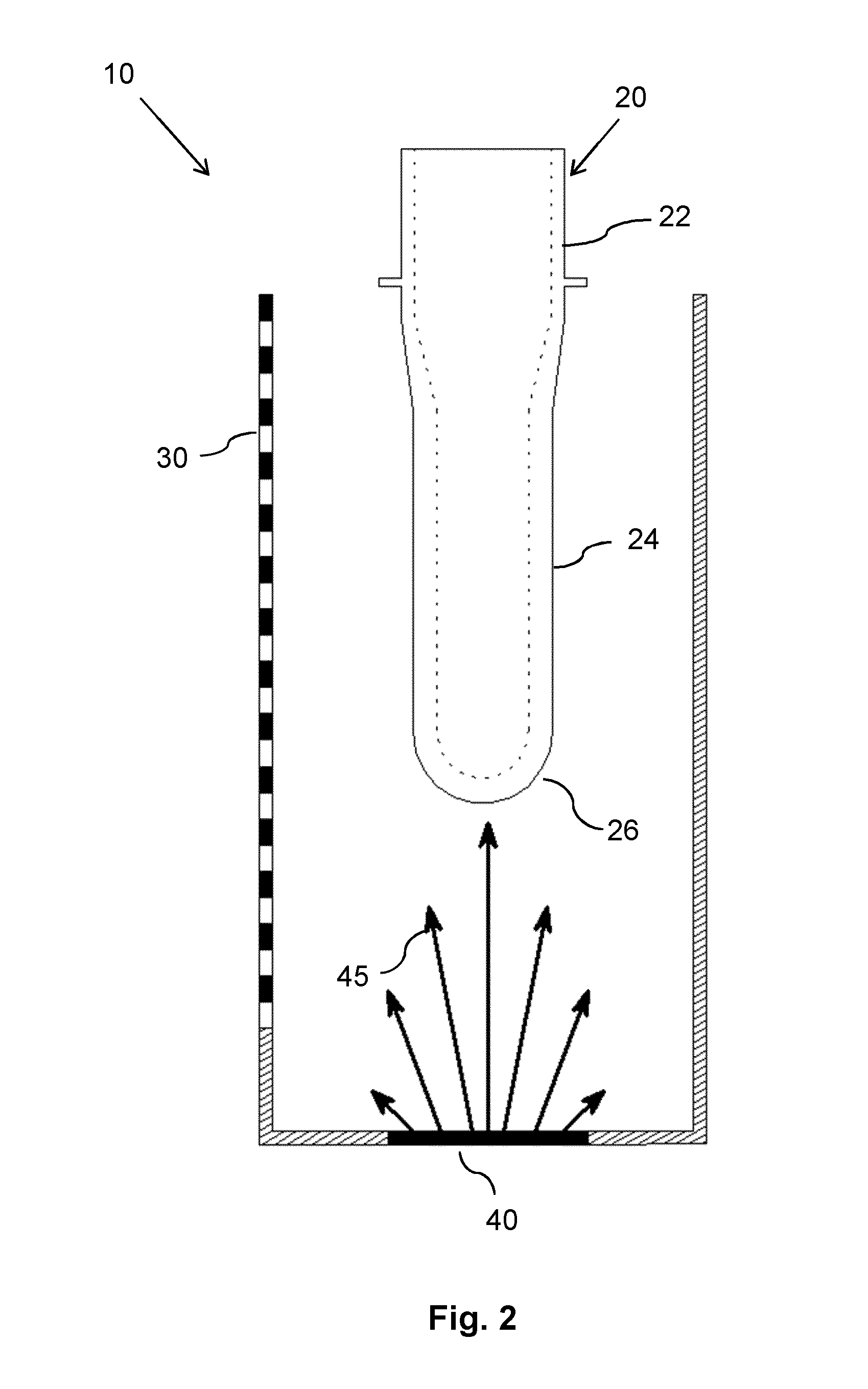
[0043]FIGS. 1 and 2 depict schematic sectional views of a first and a heating system 10 according to the present invention. The heating system 10 for heating a preform 20 comprises a laser radiation generation unit 30 for heating the sidewall of the preform 24. The preform is hold by means of a holding device (not shown). Two possible approaches are conceivable for directly heating the bottom of the preform, either a conventional halogen lamp 40 providing non laser light 45 depicted in FIG. 2 or some type of high-power laser array 50, like the VCSEL-arrays providing laser light 55 employed in the rest of the furnace or heating system 10 as depicted in FIG. 1. While the lamp-based solution might be simpler and less costly, it carries with it all the disadvantages as discussed above. However, since only a limited amount of additional energy is required, these disadvantages like minor efficiency and unintended heating of the environment and thus the heating system 10 might be acceptabl...

fourth embodiment

[0045]FIGS. 3 and 4 show schematic sectional views of a third and a heating system according to the present invention.

[0046]If no additional heat sources shall be employed, in many cases it will be possible to make use of the existing high-power VCSEL-arrays of the laser radiation generation unit 30 to directly heat the bottom of the preform 26. Typically, a bottle blowing furnace and thus the heating system 10 will have a laser module installed that has a larger height than necessary for most of the used preforms 20. In this way, the furnace has the flexibility to heat a wide range of preform heights. Thus, if a preform 20 shorter than the maximum module length is heated, the remaining lower laser zones can be employed to directly heat the preform bottom.

[0047]This most conveniently can be achieved by a reflecting device as a flat redirecting mirror 61. This mirror 61 should be arranged at an angle close to 45° to the walls of the furnace. By proper selection of the additional lase...

sixth embodiment

[0048]FIGS. 5 and 6 show schematic sectional views of a fifth and a heating system according to the present invention.

[0049]As a variant of the concept shown in FIGS. 3 and 4, also a parabolic mirror 63 may be employed. Such an arrangement would focus the laser light 55 from the additional zones, e.g. onto the center of the half-spherical bottom of the preform 26. In this way, less inhomogeneities due to refraction in the bottom of the preform 26 can be expected. A minor disadvantage of this concept may be that only half of the bottom of the preform 26 can be irradiated this way. However, since the preforms 20 are constantly rotated around their long axis during their way through the heating system 10, this disadvantage should vanish over the course of the full heating process. In another embodiment shown in FIG. 6, the parabolic mirror 63 (for the part of the preform 20 farther away from the irradiating laser unit 30) could be combined with a flat mirror 61 for the preform part clo...


PUM

PropertyMeasurementUnit
recrystallization temperatureaaaaaaaaaa
temperatureaaaaaaaaaa
angleaaaaaaaaaa

Abstract

The invention describes a heating system (10) for heating a preform (20) and a corresponding method. The preform has a neck (22), at least one sidewall (24) and a bottom (26). The heating system (10) comprises a transporting system comprising a holding device (70) to hold at least one preform (20) preferably at the neck (22) of the preform (20), the transporting system being adapted to transport the preform (20) within the heating system (10). The heating system further comprises a light providing arrangement, with at least one laser radiation generation unit (30) for heating the sidewalls of the preform (24), and a lighting equipment for directly heating the bottom of the preform (26). The heating system(10) enables an improved heating of the bottom of the preform (26) enhancing the flexibility of PET bottle blowing.

Description

FIELD OF THE INVENTION:[0001]The invention relates to a heating system for heating PET-preforms in a bottle blowing process and a corresponding method of heating PET-preforms in a bottle blowing process.BACKGROUND OF THE INVENTION:[0002]US 2012 / 0160822 A1 discloses a method of heating a preform characterized by a radius, a material thickness, and a material absorption spectrum, which method comprises the steps of selecting, depending on a desired temperature profile, a desired effective absorption coefficient for the preform on the basis of the preform radius and material thickness; generating a laser radiation beam comprising radiation with a wavelength spectrum compiled on the basis of absorption coefficients of the absorption spectrum to satisfy the effective absorption coefficient and directing the laser radiation beam at the preform to heat the preform.[0003]FR 2 976 841 A1 discloses a method of heating a preform of plastic material by means of electromagnetic radiation for pro...

Claims


Application Information

Patent Timeline
Patent Type & Authority Applications(United States)
IPC IPC(8): B29C49/64B29C35/08
CPCB29C49/6445B29C35/0805B29L2031/7158B29K2067/003B29K2105/258B29C2035/0838B29K2067/00B29C49/64B29C49/6454
Inventor POLLMANN-RETSCH, JENSHEUSLER, GERO
Owner KONINKLJIJKE PHILIPS NV
Why Eureka
Try Eureka