Light source cooling body, light source assembly, a luminaire and method to manufacture a light source cooling or a light source assembly

a cooling body and light source technology, applied in the field of cooling bodies, can solve the problems of inability to manufacture cooling fins, limited cooling capacity of heat dissipation devices, and non-functional light sources, and achieve the effect of better cooling solutions

Active Publication Date: 2020-03-03
SIGNIFY HLDG BV
View PDF30 Cites 2 Cited by
  • Summary
  • Abstract
  • Description
  • Claims
  • Application Information

AI Technical Summary

Benefits of technology

[0010]Thus, the light source cooling body is a homogeneous body which implies that it does not comprise different materials between which transition interfaces exist. The transition interfaces may comprise air and, thus, they may each form a thermal barrier. The thermal path from the interface area towards the evaporator is only through the thermally conductive material and is not obstructed by transition interfaces between different materials. Thus, the heat generated in the light source that is thermally coupled to the interface area can easily flow towards the evaporator to evaporate the cooling material (available in the liquid phase) into in the gaseous phase. The cooling material in the gaseous phase can easily flow towards the condenser via the hollow space. The condenser is away from the interface area and is consequently less warm than the direct environment of the interface area and the evaporator. Because of the lower temperature, in the condenser the cooling material may condensate thereby delivering heat from the light source to the environment of the condenser. Again, the condenser is only surrounded by the material of the light source cooling body and no other materials and / or transition interfaces prevent the transfer of heat from the cooling material in the gaseous phase to the material of the light source cooling body. Depending on the direct environment of the light source cooling body, the heat that is transferred to the material of the light source cooling body (near the condenser) may be further transferred to the direct environment. For example, when the light source cooling body is surrounded, in the environment of the condenser, by air convection may lead to the delivery of heat to the environmental air.
[0011]The above mechanism at least leads to a very good heat spreading within the light source cooling body. As such, when a light source in operation is thermally coupled to the interface area, temperature differences will be relatively small between the temperature of the light source and specific parts of the light source cooling body. Furthermore, because the temperature differences are relatively low, more heat can be conducted towards / provided to the direct environment of the light source cooling body. As such a good cooling mechanism is provided for the light source and a relatively good thermal management of a light source assembly or luminaire may be obtained when the light source cooling body is integrated in such a light source assembly or such a luminaire.
[0012]Furthermore, the fact that the light source cooling body is a homogeneous body means that the light source cooling body is a one-piece-component. Thereby, compared to the known cooling solutions in which, for example, heat pipes are used, the amount of components is reduced and no specific assembling steps are required during the production of the light source cooling body. Thereby manufacturing costs are saved. Additionally, when the light source cooling body is made of the same thermally conductive material, additive manufacturing technologies may be used to manufacture the light source cooling body. Such technologies are, for example, direct metal laser sintering, selective laser sintering, electron beam melting, fused deposition modeling, 3d printing based on extrusion and additive manufacturing based on using arc wires. In general, in an additive manufacturing technology, the component is build up in layers. Subsequently, when such additive manufacturing technologies are used, one can easily optimize the shape of the light source cooling body and the shape of the hollow space. Traditionally, when heat pipes are used, the number of bends that can be made in the heat pipes are limited because it would damage the internal structure of the heat pipe too much, while with additive manufacturing the internal structure may be optimized at every position—for example, the shape of the hollow space may be optimized.
[0015]As discussed above, the interface area comprises a protrusion having a flat surface facing away from the light source cooling body, wherein the flat surface being configured to thermally couple to a surface of a light source. For example, when the light source is a solid state light emitter, a flat contact area to the solid state light emitter is advantageous because solid state light emitters have in general a flat surface configured to be coupled to another component. The fact that the interface area comprises a protrusion creates possibilities to provide around the protrusion “lowered” electrical connections for providing power to the light source. When the solid state light emitter is coupled with its lower surface to the protrusion one may the “lowered” electrical connections to connect to the lower surface of the solid state light emitter. In particular the protrusion allows the use of so-termed flip-chip LEDs which have at least at one of their surfaces a light exit window through which light is emitted in the ambient and which have at a surface opposite the light exit window power contact areas by which the flip-chip LED has to be connected to power lines, such as the “lowered” electrical connections. The protrusions provide a good thermal path to the evaporator because they are part of the homogeneous body of the light source cooling body and the flip-chip LEDs may extends, in a plane defined by the flat surface, beyond the protrusion. In the area that they extends beyond the protrusion contact areas may be provided on the flip-chip LEDs for begin connected to power lines. In other words, the protrusion provides an advantageous way of coupling light sources to the light source cooling body when the light source has a light exit window at a top surface and has at a bottom surface (opposite the top surface) electrical contact—the bottom surface may be coupled to the protrusion and at least a portion of the bottom surface with the electrical contacts may extend beyond the protrusion such that the electrical contacts may be coupled to powerlines.
[0040]Examples of additive manufacturing technologies are, for example, direct metal laser sintering, selective laser sintering, fused deposition modeling, 3d printing based on extrusion and additive manufacturing based on using an arc wire. When such additive manufacturing technologies are used, one can easily optimize the shape of the light source cooling body and the shape of the hollow space. Traditionally, when heat pipes are used, the number of bends that can be made in the heat pipes are limited because it would damage the internal structure of the heat pipe too much, while with additive manufacturing the internal structure may be optimized at every position—for example, the shape of the hollow space may be optimized. Also, the above manufacturing method builds up the light source cooling body as a homogeneous component made of (optionally) one material. Thereby it is ensured that no interfaces are present in the light source cooling body with a relatively high thermal resistance. Thus, the manufacturing technology enables the manufacturing of light source cooling bodies which provide a better cooling of a light source. In an optional embodiment, the light source cooling body that is build up in layers is sintered afterwards.

Problems solved by technology

When a LED becomes too hot, the LED may become permanently damaged resulting in a non-functional light source.
The cooling capacity of the heat dissipation device is limited by the amount of heat that can be transferred between the different elements (LED-heat spreaders-heat pipe-base) and, finally, to the environment.
Furthermore, the cooling capacity of the base strongly depends on manufacturing limitations of such a base—for example, with known manufacturing technologies like extrusion or molding it is almost impossible to manufacture cooling fins that provide an optimum between a size of a surface in contact with the environmental air, conduction of heat by the fins, and space for environmental air to flow through the cooling fins.
Thus, the heat dissipation device is capable of cooling LEDs, but has also limitations in its cooling capacity.
There is a tendency to increase the power of the LEDs and the heat dissipation device of the cited patent application lacks cooling capacity for such high power LEDs.

Method used


Image

  • Light source cooling body, light source assembly, a luminaire and method to manufacture a light source cooling or a light source assembly
  • Light source cooling body, light source assembly, a luminaire and method to manufacture a light source cooling or a light source assembly
  • Light source cooling body, light source assembly, a luminaire and method to manufacture a light source cooling or a light source assembly

Examples


Embodiment Construction

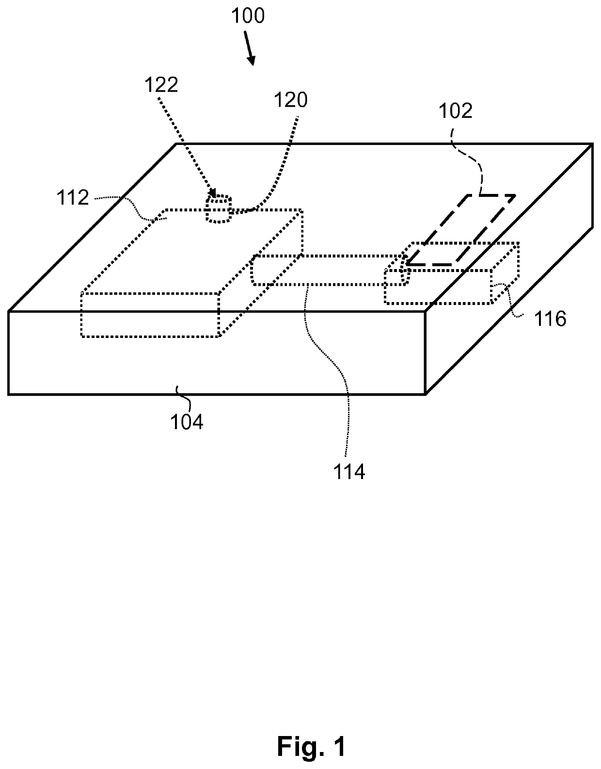
[0062]FIG. 1 schematically shows a light source cooling body 100 according to the invention. The light source cooling body 100 comprises a homogeneous body 104 of a single material that is thermally conductive. Inside the homogeneous body 104 is provided a hollow space that is formed in the example of FIG. 1 by spaces 112, 114 and 116. The hollow space may optionally comprise a small channel 120 to the outside surface of the light source cooling body 100 such that at the outside surface of the light source cooling body 100 is provided a sealable opening that may be used to pump the hollow space empty and provide a cooling material into the hollow space. The walls of the hollow space are formed by the material of the homogeneous body 104. Thus, no additional materials are provided in between the hollow space and the homogeneous body 104. Space 116 is configured as an evaporator in which a cooling material present in a liquid phase and which is evaporated when heat is received by the ...


PUM


Abstract

A light source cooling body (100), a light source assembly, a luminaire and a method to manufacture a light source cooling body or a light source assembly are provided. The light source cooling body comprises a homogeneous body (104) made of a thermally conductive material. The homogenous body comprises an open space that comprises a wick structure, a condenser (112) and an evaporator (116). Near the evaporator the light source cooling body has an interface area (102) to thermally couple with a light source and to receive heat from the light source. The condenser is arranged away from the interface area. A portion 114 of the open space is tubular shaped. The open space may hold a cooling liquid partially in the gaseous phase and partially in the liquid phase and the wick structure is configured to transport the cooling material in the liquid phase towards the evaporator.

Description

CROSS-REFERENCE TO PRIOR APPLICATIONS[0001]This application is the U.S. National Phase application under 35 U.S.C. § 371 of International Application No. PCT / EP2015062634, filed on Jun. 8, 2015, which claims the benefit of European Patent Application No. 14177929.9, filed on Jul. 22, 2014. These applications are hereby incorporated by reference herein.FIELD OF THE INVENTION[0002]The invention relates to the field of cooling bodies to which a light source may be coupled to cool the light source. The invention also relates to light source assemblies, luminaires, methods to manufacture such cooling bodies and methods to manufacture a light source assembly.BACKGROUND OF THE INVENTION[0003]Heat management is important in light sources, in particular when solid state light emitters like Light Emitting Diodes (LEDs) are used as light emitter. LEDs generate on a relatively small area a relatively large amount of light and a relatively large amount of heat that must somehow be conducted towa...

Claims


Application Information

Patent Timeline
Patent Type & Authority Patents(United States)
IPC IPC(8): F21V29/503H01L33/58H01L33/62H01L33/64F21V29/85F21V29/87F21V29/89F21V29/76F21V29/61F21V29/58F21V29/57
CPCF21V29/87F21V29/763F21V29/503F21V29/767H01L33/58F21V29/57F21V29/86H01L33/62F21V29/89F21V29/61H01L33/642H01L33/648F21V29/58H01L33/641H01L2933/0066H01L2933/0075H01L23/427H01L2924/0002F21V29/505F21V29/51F21V29/70F21Y2115/30F21Y2115/10H01L2924/00
Inventor KADIJK, SIMON EMETREURNIET, THEODOOR CORNELISGOLDBACH, SUSANNE LINA
Owner SIGNIFY HLDG BV
Why Eureka
Try Eureka