Waste toner transporting apparatus and toner cartridge having the same

a technology of waste toner and transporting apparatus, applied in the field of toner cartridges, can solve the problems of reducing reducing the efficiency of the waste toner transporting apparatus, and increasing the manufacturing cost, so as to reduce the size of the waste toner housing and limit the occurrence of operation errors

Active Publication Date: 2006-07-20
HEWLETT PACKARD DEV CO LP
View PDF2 Cites 25 Cited by
  • Summary
  • Abstract
  • Description
  • Claims
  • Application Information

AI Technical Summary

Benefits of technology

[0020] An aspect of the present invention is to address at least the above problems and / or disadvantages and to provide at least the advantages described below. Accordingly, an aspect of the present invention is to provide a waste toner transporting apparatus and a toner cartridge with the same which reduce the size of the waste toner housing due to, for example, a structure in which an additional film fixing member and a vibrating shaft are not necessary. Moreover, the waste toner apparatus according to an aspect of the present invention may limit the occurrence of operation errors.
[0021] Another object of the present invention is to provide a waste toner transporting apparatus and a toner cartridge with the same which may reduce manufacturing costs by limiting the amount of sealing members used for the waste toner housing.
[0027] In the waste toner transporting apparatus and the toner cartridge, as described in the exemplary implementations above, since the additional film fixing member and vibrating shaft requiring a space are not utilized, the size of the toner waste housing may be reduced, and operation errors of the apparatus can be limited.
[0028] In addition, since the toner transporting plate vibrates from side to side through a cam hole formed on one side surface of the waste toner housing, the waste toner according to an exemplary implementation may reduce manufacturing costs by limiting the amount of seals necessary to prevent leakage.

Problems solved by technology

However, one drawback of the conventional waste toner transporting apparatuses 30 as described above, is that since the film fixing member 32 and the vibration shaft 33 occupy a space of the waste toner housing 23, in order to receive an amount of waste toner which is same as a volume of the waste toner housing, the waste toner housing 23 should have a relatively large size.
Additionally, a problem arises in that since the film fixing member 32 and the vibrating shaft 33 vibrate from side to side in the entire space of the waste toner housing 23, once the waste toner received in the waste toner housing solidifies, the waste toner transporting apparatus 30 may not operate normally.
Therefore, manufacturing costs may increase.

Method used


Image

  • Waste toner transporting apparatus and toner cartridge having the same
  • Waste toner transporting apparatus and toner cartridge having the same
  • Waste toner transporting apparatus and toner cartridge having the same

Examples


Embodiment Construction

[0039] The matters defined in the description such as a detailed construction and elements are provided to assist in a comprehensive understanding of the embodiments of the invention. Accordingly, those of ordinary skill in the art will recognize that various changes and modifications of the embodiments described herein can be made without departing from the scope and spirit of the invention. Also, descriptions of well-known functions and constructions are omitted for clarity and conciseness.

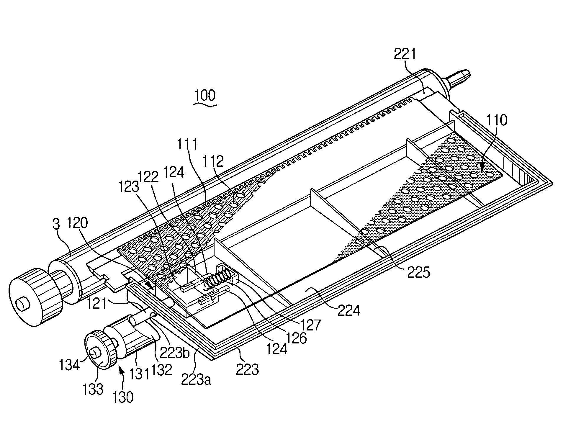
[0040] Referring to FIG. 3, a waste toner transporting apparatus 100 according to an exemplary implementation of the present invention comprises a toner transporting plate 110, a transporting member 120 and a driving cam 130.

[0041] The toner transporting plate 110 is arranged above a cleaning blade 221. On a side of the cleaning blade 221, a waste toner housing 223 which receives the waste toner transported by the toner transporting plate 110 is provided below the toner transporting plate 110....


PUM


Abstract

A waste toner transporting apparatus which transfers waste toner removed from a photosensitive drum to a waste toner housing is provided. The waste toner transporting apparatus includes a toner transporting plate arranged substantially above a cleaning blade. A transporting member is installed at one end of the toner transporting plate and has a cam follower arranged on an opposite side of the toner transporting plate. A driving cam contacts the cam follower and converts rotational motion into linear reciprocating motion to enable the toner transporting plate to reciprocate on the cleaning blade.

Description

CROSS-REFERENCE TO RELATED APPLICATIONS [0001] This application claims the benefit under 35 U.S.C. § 119(a) of Korean Patent Application No. 2005-4987, filed on Jan. 19, 2005, the entire disclosure of which is hereby incorporated by reference. BACKGROUND OF THE INVENTION [0002] 1. Field of the Invention [0003] The present invention relates to a toner cartridge used in the image forming apparatus. More particularly, the present invention relates to a waste toner transporting apparatus which is provided in the toner cartridge and transports the waste toner removed from a photosensitive drum. [0004] 2. Description of the Related Art [0005] In general, the electrophotographic type image forming apparatus is the printing apparatus in which an electrostatic latent image formed on a surface of a photosensitive drum is developed by a toner to form a visible image. Then, the developed visible image is transferred to a printing medium. However, after the visible image is transferred to the pr...

Claims


Application Information

Patent Timeline
Patent Type & Authority Applications(United States)
IPC IPC(8): G03G21/00
CPCG03G21/0011G03G2221/1624G03G21/105B24B27/0023B24B27/0069B24B29/00B24D13/02
Inventor CHOI, SAM-SEOKPARK, DONG-HOON
Owner HEWLETT PACKARD DEV CO LP
Why Eureka
Try Eureka