Swaged synthetic cable terminations

a synthetic cable and termination technology, applied in the direction of cables, ropes, vehicles/pulleys, etc., can solve the problems of high pressure, kink and distort the individual strands, and the field of synthetic cables has not traditionally enjoyed this flexibility or economy

Active Publication Date: 2006-07-20
BRIGHT TECH CO LTD
View PDF1 Cites 31 Cited by
  • Summary
  • Abstract
  • Description
  • Claims
  • Application Information

AI Technical Summary

Benefits of technology

[0050]FIG. 25 is a partial section view, showing the use of a plug to reinforce a swaged connection.

Problems solved by technology

The field of synthetic cables has not traditionally enjoyed this flexibility or economy, since the prior art approach for creating swaged terminations does not work well for synthetic cables.
The strands also tend to be quite slick.
These high pressures tend to kink and distort the individual strands, since synthetic strands tend to have poor compressive resistance.
Thus, the techniques described in FIGS. 1 and 2 are ill suited for use with synthetic cables.
Thus, the hardware traditionally used for terminating a synthetic cable is ill-suited for use with standard rigging fixtures traditionally used for terminating wire rope.

Method used


Image

  • Swaged synthetic cable terminations
  • Swaged synthetic cable terminations
  • Swaged synthetic cable terminations

Examples


Embodiment Construction

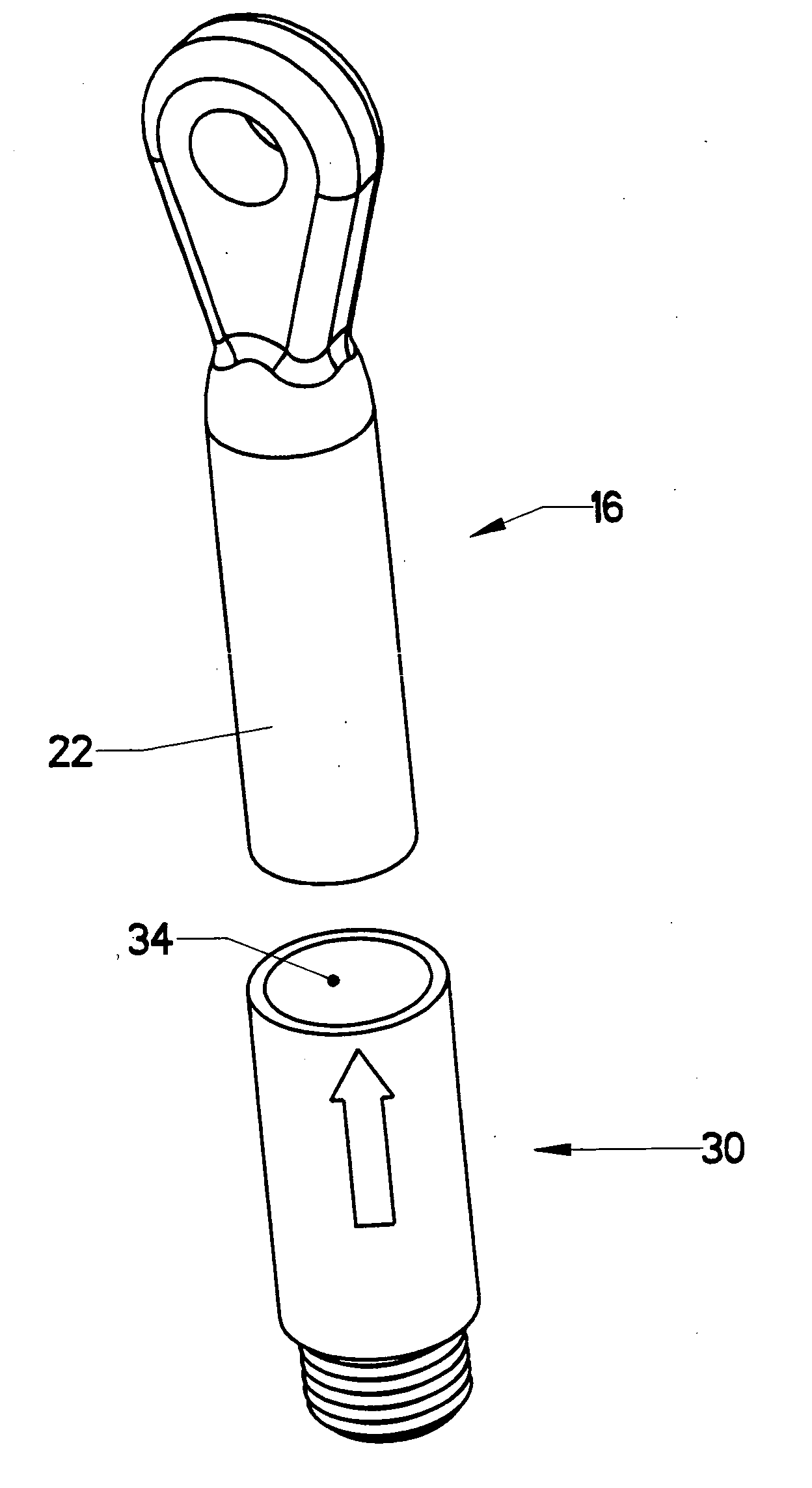
[0059] A goal of the present invention is to allow the use of standard rigging fixtures with terminations suitable for use on synthetic cables. FIG. 6 depicts an assembly which can accomplish this goal. Prior art anchor 18—as shown in FIG. 4—has been modified by adding a male thread to a portion of its outer surface. The revised anchor is designated male threaded anchor 26. Its internal features are similar to the prior art anchor. It contains an expanding cavity which securely holds the potted strands on the end of cable 10. The expanding cavity can assume many forms in addition to the conical shape shown.

[0060] Threaded coupler 28 screws over the male threads on the outside of male threaded anchor 26. The reader will note that threaded coupler 28 includes an internal (female) thread running from one end to the other. Swaging coupler 30 includes male thread 31, which is sized to screw into threaded coupler 28. Thus, male threaded anchor 26, threaded coupler 28, and swaging coupler...


PUM


Abstract

A connecting system which allows a standard rigging fixture to be connected to a synthetic cable termination by swaging. The cable termination is provided with a swaging sleeve. When the standard rigging fixture is placed next to the termination, this swaging sleeve is swaged over a portion of the standard rigging fixture in order to lock the standard rigging fixture to the termination. The provision of the swaging sleeve on the termination is accomplished using a variety of approaches, including forming the swaging sleeve as part of an anchor, providing a separate swaging sleeve attached by threads, and forming the anchor and swaging sleeve with two separate swaging operations.

Description

CROSS-REFERENCES TO RELATED APPLICATIONS [0001] This is a non-provisional patent application claiming the benefit, under 37 CFR §1.53, of several earlier-filed provisional applications. The earlier-filed applications are as follows: Ser. No.Named Inventor(s)Filing Date60 / 644,169Richard V. Campbell,Jan. 14, 2005Kevin J. Barefield60 / 644,170Richard V. Campbell,Jan. 14, 2005Kevin J. Barefield60 / 693,687Richard v. CampbellJun. 24, 2005STATEMENT REGARDING FEDERALLY SPONSORED RESEARCH OR DEVELOPMENT [0002] Not Applicable. MICROFICHE APPENDIX [0003] Not Applicable BACKGROUND OF THE INVENTION [0004] 1. Field of the Invention [0005] This invention relates to the field of synthetic cables. More specifically, the invention comprises devices for attaching standard cable rigging fixtures to an end of a synthetic cable using swaging techniques. [0006] 2. Description of the Related Art [0007] Devices for mounting a termination on the end of a wire, rope, or cable are disclosed in detail in copendin...

Claims


Application Information

Patent Timeline
Patent Type & Authority Applications(United States)
IPC IPC(8): H01R4/10H01R9/05A44B99/00
CPCF16G11/02F16G11/04Y10T24/47Y10T24/4755Y10T403/4908Y10T24/398Y10T24/4764F16G11/025F16G11/042F16G11/046F16G11/048F16G11/05
Inventor CAMPBELL, RICHARD V.BAREFIELD, KEVIN J.
Owner BRIGHT TECH CO LTD
Why Eureka
Try Eureka