Swaging feedback control method and apparatus

a feedback control and swaging technology, applied in the direction of forging/pressing/hammering apparatus, forging safety devices, forging presses, etc., can solve the problems of frequent tool repairs and part replacement, wear and tear of swaging tools, and the potential for variations in the diameter or other dimension of swaged work pieces

Inactive Publication Date: 2005-01-25
BARTROM MICHAEL A +1
View PDF23 Cites 16 Cited by
  • Summary
  • Abstract
  • Description
  • Claims
  • Application Information

AI Technical Summary

Benefits of technology

Thus, the above embodiment swages a subsequent work piece based in part on measurements of the first work piece. Both of the above described embodiments can produce parts having consistent dimensions despite wear on the swaging tool and the associated die. For example, as the die wears, which otherwise causes error in the swaging operation, the swaging stroke is merely increased to compensate for the die wear, thereby producing consistent swaging workpieces throughout much or all of the useful life of the die.

Problems solved by technology

As portions of the swaging tool experience wear, however, there is a potential for variations in the diameter or other dimension of the swaged work piece.
However, frequent tool repairs and part replacement can be costly and time consuming.
Nevertheless, infrequent tool repairs and part replacement can undesirably increase the error margin in the dimensions of the final swaged product.

Method used


Image

  • Swaging feedback control method and apparatus
  • Swaging feedback control method and apparatus
  • Swaging feedback control method and apparatus

Examples


Embodiment Construction

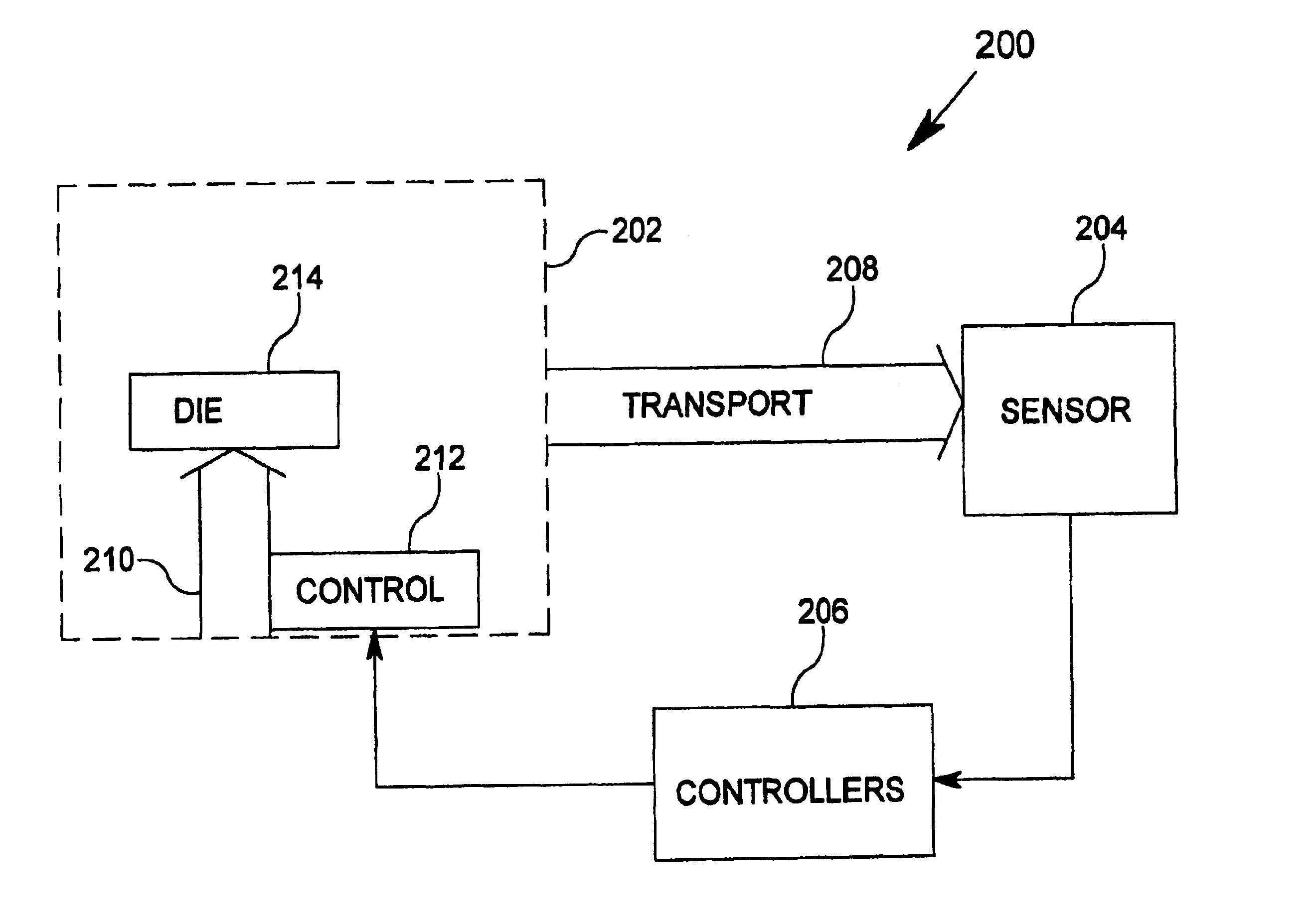
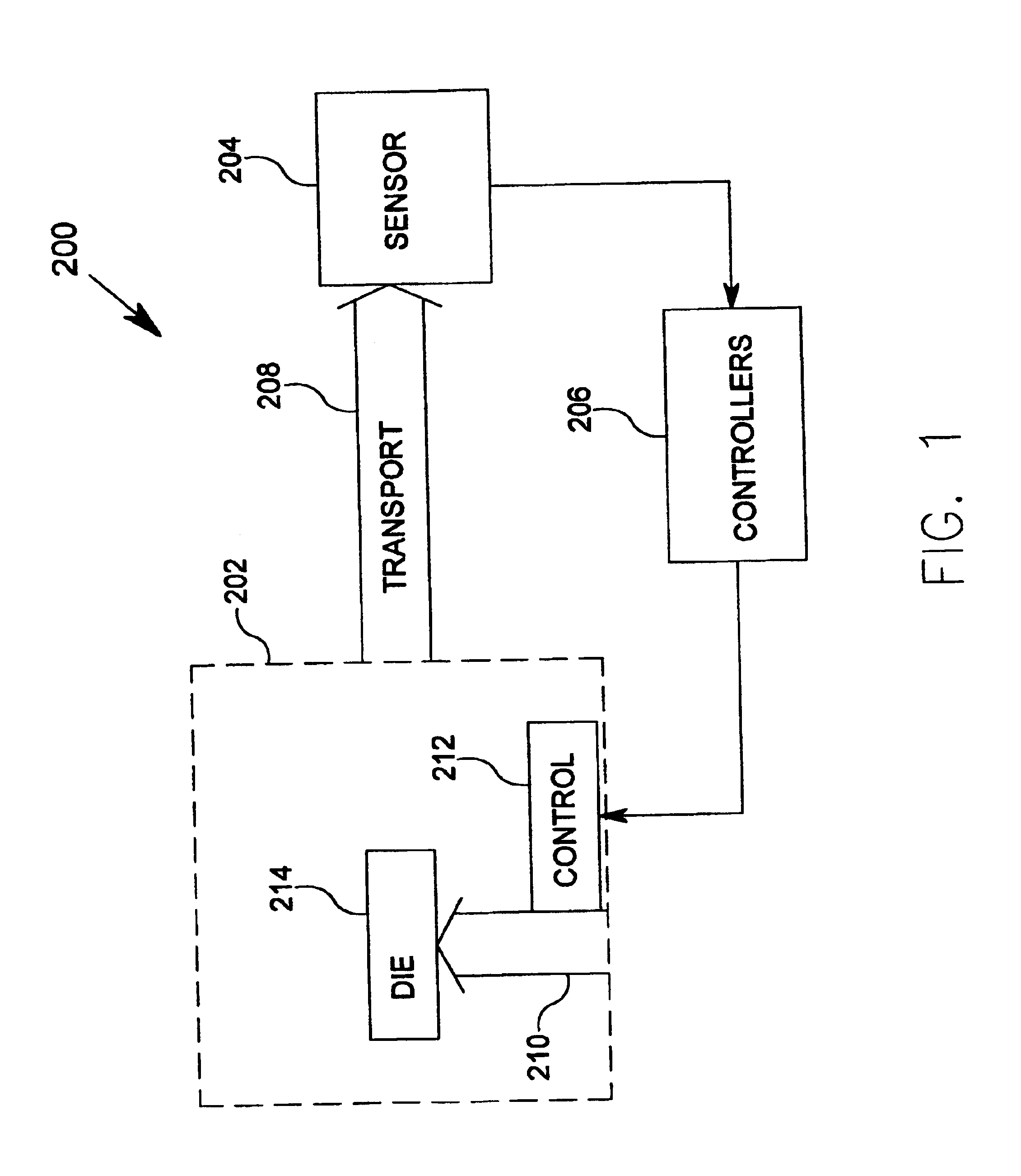
FIG. 1 shows an exemplary embodiment of a swaging feedback control system 200 according to the present invention. The swaging feedback control system 200 includes a swaging assembly 202, a sensor assembly 204, a controller 206, and a transport mechanism 208.

The swaging assembly 202 includes a movable tool 210, a drive control mechanism 212, and a die or contact element 214. The movable tool 210 is configured to exert force on the die 214 under the control of the drive control mechanism 212. To this end, the movable tool 210 may comprise a hydraulic cylinder having a controllable stroke length. However, it will be appreciated that other drive mechanisms may be used, preferably those with controllable stroke lengths. The drive control mechanism 212 is operable to control the operation of the movable tool responsive to signals received from the controller 206. For example, the drive control mechanism 212 may be a servo controller device, as is known in the art.

The die 214 is configured...


PUM

PropertyMeasurementUnit
radial widthaaaaaaaaaa
heightaaaaaaaaaa
thicknessaaaaaaaaaa

Abstract

A swaging system includes a swaging assembly, a sensor, and a controller. The swaging assembly includes a movable tool, the movable tool operate to exert force on a die. The die is configured to reduce a dimension of a work piece responsive to the exerted force, the dimension reduction having a relationship to a stroke of the movable tool. The sensor is operable to obtain information including a measurement of the reduced dimension of the work piece. The sensor is operable to generate a measurement signal representative of the obtained information. The controller is operably coupled to receive the measurement signal from the sensor, and is operable to cause adjustment the stroke of the movable tool responsive to the measurement signal.

Description

FIELD OF THE INVENTIONThe present invention relates generally to the field of machine tools, and more particularly, to the field of tools that operate to reduce the size or diameter of a work piece, or swaging tools.BACKGROUND OF THE INVENTIONSwaging is a method that is employed to reduce the diameter or thickness of a rod-like or tube-like structure. Swaging may be carried out by forging, squeezing or hammering the work piece. In one type of swaging tool, the work piece is fed into an opening formed by a plurality of die segments arranged generally surrounding the opening. The die segments are forced radially inward to a predetermined point. As the die segments travel radially inward, they converge on the work piece and strike the outer diameter of the work piece, thereby tending to reduce the diameter of the work piece. To force the die segments inward, a movable tool assembly often engages the outside of the die segments to push them radially inward.After the swaging operation, t...

Claims


Application Information

Patent Timeline
Patent Type & Authority Patents(United States)
IPC IPC(8): B21J7/14B21J9/00B21J9/06B21J7/00
CPCB21J9/06B21J7/14
Inventor BARTROM, MICHAEL A.BRODT, JEFFREY A.
Owner BARTROM MICHAEL A
Why Eureka
Try Eureka