
System and method for controlling force applied to and manipulation of medical instruments

a technology of controlling force and manipulating force, applied in the field of system and method for controlling force applied to manipulating medical instruments, can solve the problems of difficult simultaneous manipulation of multiple degrees of freedom achieve the effects of quick exchange of working channel tools, smooth movement of current tools, and rapid movement of tools

Inactive Publication Date: 2006-07-20
IMMERSION MEDICAL
View PDF42 Cites 160 Cited by
  • Summary
  • Abstract
  • Description
  • Claims
  • Application Information

AI Technical Summary

Benefits of technology

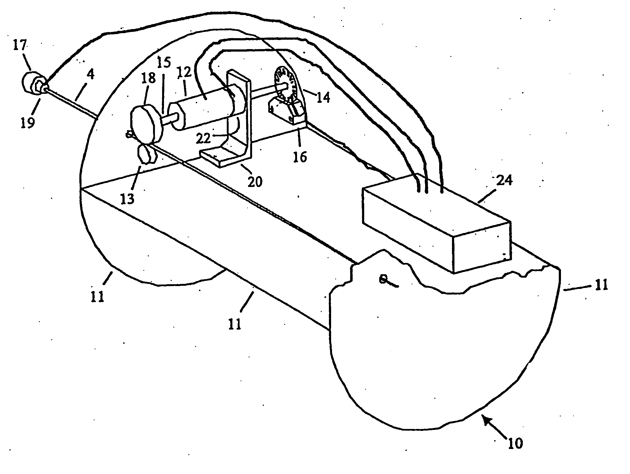
[0006] In one mode of use, the system uses drive wheels driven by a motor or other device to permit the practitioner to quickly exchange working channel tools, by smoothly moving the current tool out of the working channel, and then quickly moving in the new tool to a point just short of exiting the working channel. At this point the practitioner takes over and performs the fine motor skills necessary to move the tool out of the endoscope and into a position to interact with the anatomy. In another mode of operation the physician manipulates tools manually and is provided with tactile guidance via a set of driven or braked drive wheels. One form of guidance is the provision of notification that the tool is approaching the end of the endoscope and is about to emerge from the endoscope. A braking or other tactile force would signal nearing the end of the working channel, enabling the user to move the tool quickly within the working channel without danger of moving the tool too rapidly out of the working channel, thereby reducing the risk of damage or injury to tissue adjacent the distal end of the endoscope.

Problems solved by technology

The tasks of manipulating and stabilizing the three or more degrees of freedom of the endoscope, while simultaneously manipulating the multiple degrees of freedom of the working channel tool are difficult to perform, and frequently the practitioner uses an assistant to manipulate one or more of the degrees of freedom, such as working channel tool actuation.

Method used


Image

  • System and method for controlling force applied to and manipulation of medical instruments
  • System and method for controlling force applied to and manipulation of medical instruments
  • System and method for controlling force applied to and manipulation of medical instruments

Examples


Embodiment Construction

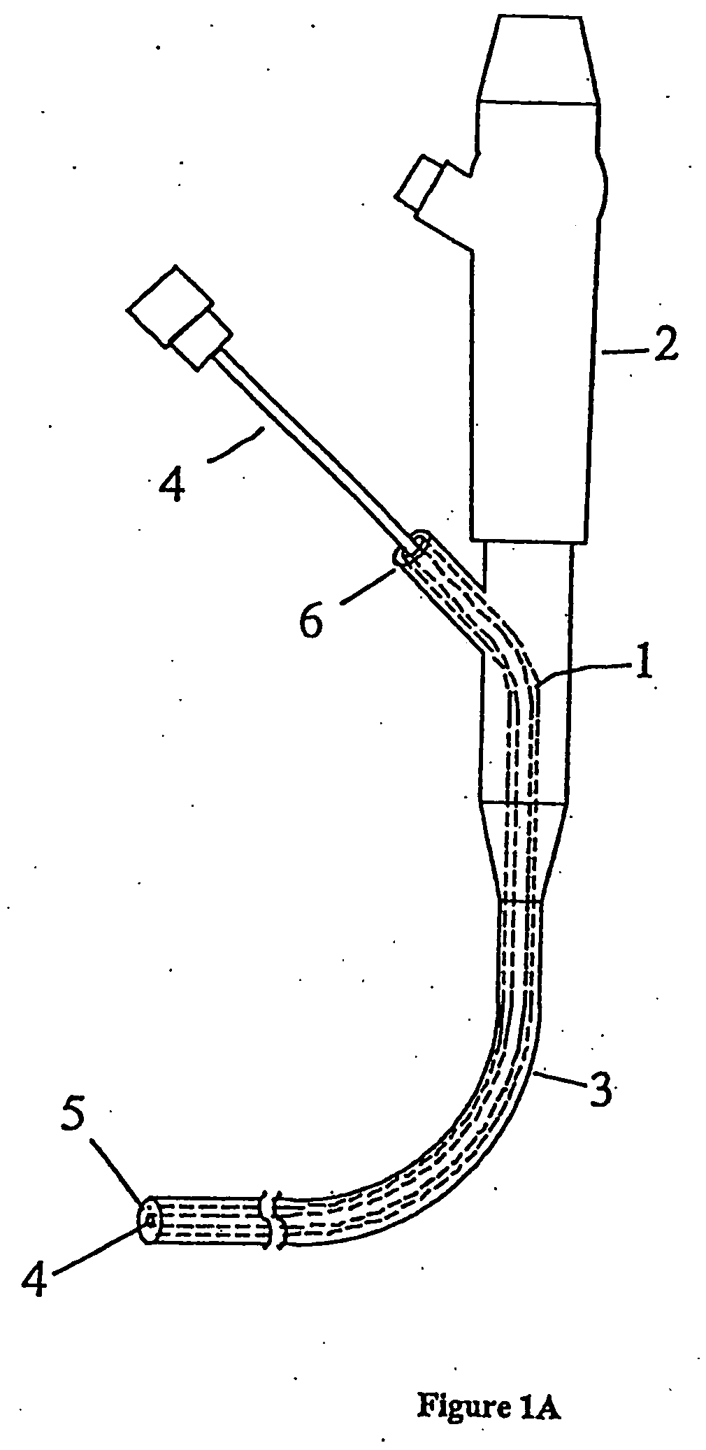
[0019]FIG. 1a illustrates an unmodified endoscope of the prior art, showing the endoscope body 2 attached to the endoscope tube assembly 3. Working channel tool 4 is inserted into working channel orifice 6 in endoscope body 2. Working channel tool 4 slides through working channel tube 1 and exits the distal end of endoscope tube assembly 3 through working channel orifice 5.

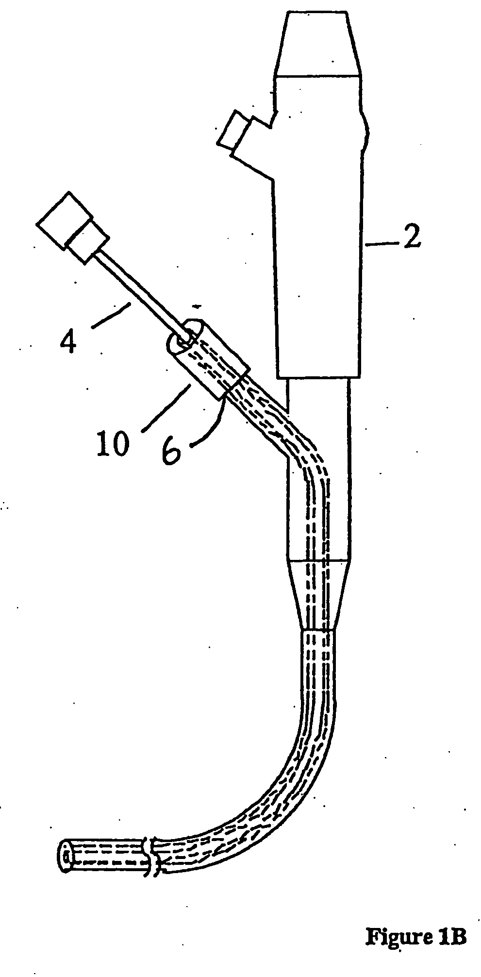
[0020]FIG. 1b illustrates one embodiment of a motion sensor and control element 10 of the present invention, which is affixed to the working channel orifice 6 of an endoscope. Working channel tool 4 passes through motion sensor and control element 10 and through working channel orifice 6. Normal manipulation and operation of the working channel to possible through the body of motion sensor and control element 10. Motion sensor and control element 10 can assist in the control of the working channel tool 4, as exemplified in the embodiments presented below.

[0021] The working tool 4 may be any of a variety of medic...


PUM


Abstract

Apparatus for controlling force applied to and for manipulation of a surgical instrument. Movement and / or forces applied to the surgical instrument are preferably sensed within the apparatus. An actuator is preferably used to apply force to the surgical instrument for control and manipulation of the instrument. The apparatus applies variable force feedback to apply force to the surgical instrument in one or more degrees of freedom to provide an enhanced haptic experience to the user.

Description

STATEMENT OF RELATED APPLICATION(S) [0001] The present application is a continuation-in-part of co-pending U.S. patent application Ser. No. 10 / 390,715, filed Mar. 19, 2003, by Gregory L. Merril et al. and entitled, “System and Method for Controlling Force Applied to and Manipulation of Medical Instruments,” which, in turn, is a divisional and claims priority based to U.S. patent application Ser. No. 09 / 811,358, now U.S. Pat. No. 6,817,973, filed Mar. 16, 2001, by Gregory L. Merril et al. and entitled, “Apparatus for Controlling Force For Manipulation of Medical Instruments,” which claims priority to Provisional Patent Application Ser. No. 60 / 189,838, filed on Mar. 16, 2000, by Gregory L. Merril et al. and entitled, “System and Method for Controlling Force Applied to and Manipulation of Medical Instruments,” all commonly owned herewith and hereby incorporated by reference herein.BACKGROUND OF THE INVENTION [0002] Minimally invasive techniques for providing medical examinations and th...

Claims


Application Information

Patent Timeline
Patent Type & Authority Applications(United States)
IPC IPC(8): A61B1/00A61B1/018A61B17/00A61B17/28A61B17/32A61B17/34A61B19/00
CPCA61B1/018A61B17/29A61B17/320068A61B17/3417A61B17/3421A61B19/22A61B19/30A61B2017/003A61B2019/2292A61B2019/464A61B2019/465A61B2019/5259A61M2025/0008A61B2090/064A61B34/70A61B34/76A61B90/03A61B2090/065A61B2034/2059
Inventor MERRIL, GREGORY L.CUNNINGHAM, RICHARD L.BROWN, J. MICHAELCOHEN, ROBERT F.FELDMAN, PHILIP G.
Owner IMMERSION MEDICAL
Learn More