Optical disk drive apparatus

a technology of optical disk drive and optical drive shaft, which is applied in the direction of disposition/mounting of heads, coupling device connections, instruments, etc., can solve the problems of reducing the yield of multi-layer writing portions, affecting the reliability of the connection, and affecting the accuracy of the positioning of narrow pitch portions, etc., to achieve low cost and reliability.

Inactive Publication Date: 2006-07-20
HITACHI MEDIA ELECTORONICS CO LTD
View PDF6 Cites 19 Cited by
  • Summary
  • Abstract
  • Description
  • Claims
  • Application Information

AI Technical Summary

Benefits of technology

[0013] The object of the present invention is to provide an optical disk drive apparatus which exhibits functions required for a high-performance optical pick-up device, so as to be capable of being thinned and regenerating and recording not only a CD but also a DVD meeting various standards, and which is provided with a flexible substrate that is manufactured at a low cost and with reliability.
[0015] Electrical connection between the first flexible substrate and the second flexible substrate is made by overlapping “wiring conductors on a first connection end portion of the first flexible substrate” and “wiring conductors on a second connection end portion of the second flexible substrate” each other at the region adjacent to (in the vicinity of) an end portion of the case for optical pick-up (e.g. on the case for optical pick-up) and connected to one another through joining material. The opposite end of the second flexible substrate relative to the second connection end portion may be inserted into the connector on the side of the drive. A connection section in which the wiring conductors of the first connection end portion and the wiring conductors of the second connection end portion are connected to each other at the at the portions adjacent end portions thereof is pressed down by a cover attached to the optical pick-up case (for example, upper side) for protecting the optical pick-up device body, whereby connection strength between the wiring conductors can be ensured.
[0029] In accordance with the present invention, it is possible to realize an optical disk drive apparatus which exhibits functions required for a high-performance optical pick-up device, so as to be capable of being thinned and regenerating and recording not only a CD but also a DVD meeting various standards, and which is provided with a flexible substrate that is manufactured at a low cost and with reliability.

Problems solved by technology

Therefore, when it is required to produce the printed circuit board in which a multi-layer wiring portion and a single-layer wiring portion are integrated with each other, a cost problem in which the yield of sth of the multi-layer writing portions is reduced arises.
Therefore, as compared to a precision in drill through-holes in the flexible substrate according to the technique described in the above-mentioned Patent Document 1, a precision in positioning of the narrow pitch portion is serious.
As a result, there is also a problem that connecting yield is considerably reduced.
While the technique described in the above-mentioned Patent Document 3 is effective for an optical pick-up device having an allowance in thickness, it is not applicable to an optical pick-up device having a limited thickness, or so-called thin optical pick-up device, since the thickness limitation is serious and a connector can not be connected to the flexible substrate in the optical pick-up device.

Method used


Image

  • Optical disk drive apparatus
  • Optical disk drive apparatus
  • Optical disk drive apparatus

Examples


first embodiment

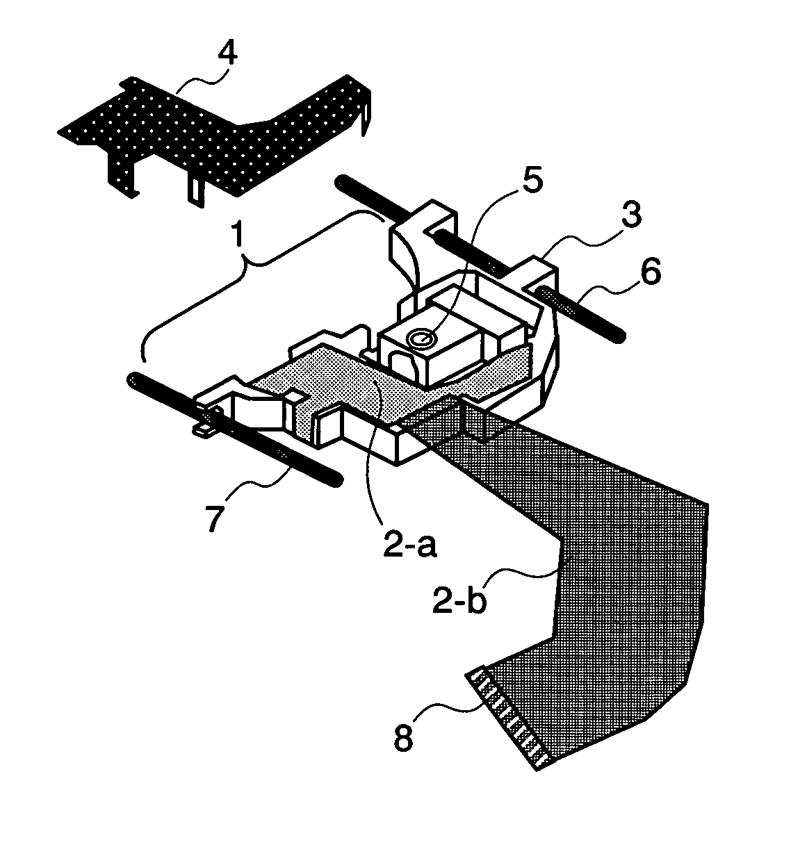
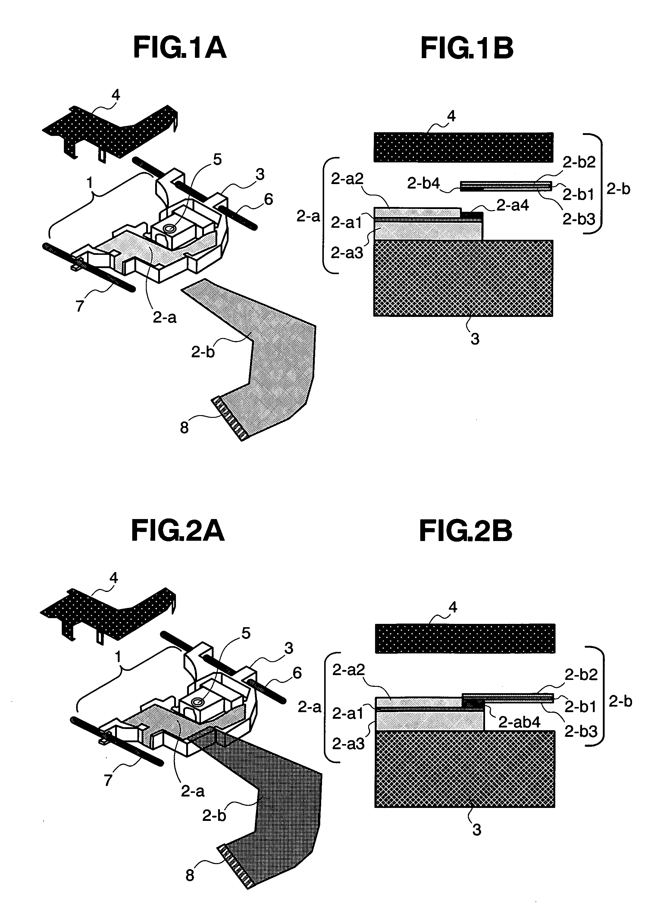
[0069] Now, a method for making connection between the first flexible substrate (2-a) and the second flexible substrate (2-b) according to a first embodiment of the present invention will be discussed hereinafter with reference to FIGS. 1A to 6.

[0070]FIG. 6 is a flow chart schematically exhibiting a procedure for manufacturing the optical pick-up device according to the present invention.

[0071] The method for manufacturing the optical pick-up device comprises the steps of die-cutting flexible substrates from the mother member that is supplied in a sheet-form (S41), thereafter mounting the LSI chip component onto the first flexible substrate (2-a), which is to be finally secured to the optical pick-up device body 1, by fixing the LSI chip component onto the first flexible substrate (2-a) via solder material such as solder paste and causing the LSI chip component to be electrically connected to the first flexible substrate by reflowing the solder material (S42), thereafter causing a...

second embodiment

[0083] Referring now to FIG. 8, a method for making connection between the first flexible substrate (2-a) and the second flexible substrate (2-b) according to a second embodiment of the present invention will be discussed hereinafter. FIG. 8 is a schematic view illustrating the method according to the second embodiment of the present invention. The second embodiment is different from the first embodiment in that the first flexible substrate (2-a) and the second flexible substrate (2-b) are connected to each other vice versa in the height direction of the optical pick-up device and the first flexible substrate (2-a) is secured by the metallic cover 4 fixedly mounted to the case 3 for optical pick-up. Incidentally, in the case where the LSI chip component is not mounted on the side of the metallic cover 4 but is mounted on the side of the case 3 for optical pick-up, if making connection between the first flexible substrate and the second flexible substrate is carried out by using the ...

third embodiment

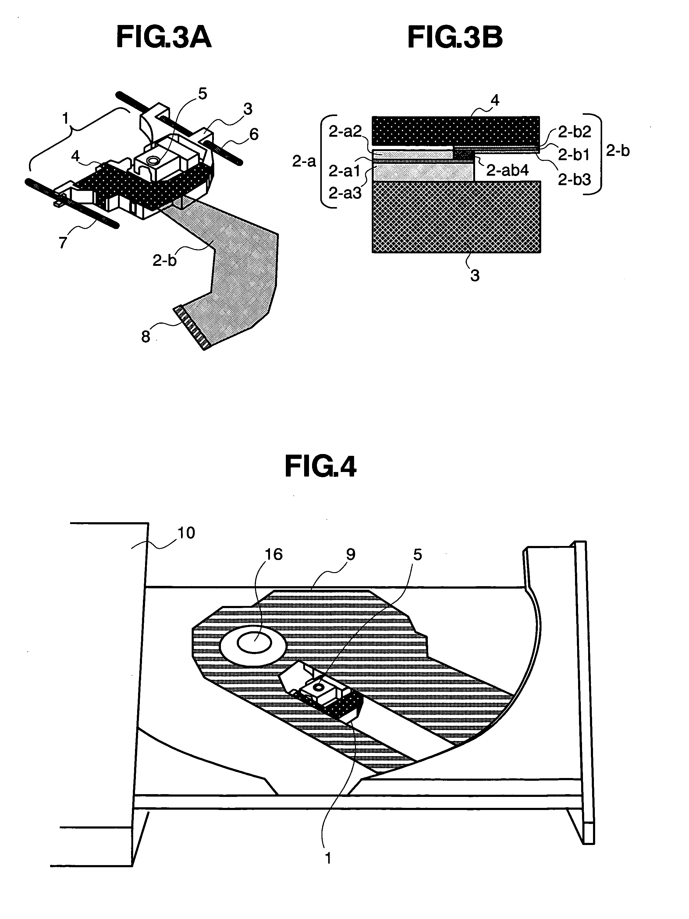
[0084] Referring to FIG. 9, a method for making connection between the first flexible substrate (2-a) and the second flexible substrate (2-b) according to a third embodiment of the present invention will be discussed hereinafter. FIG. 9 is a schematic view illustrating the third embodiment. The third embodiment is different from the first and second embodiments in that connection end portions of the first and second flexible substrates are bent in the height direction of the optical pick-up device (in the vertical direction), superposed in a horizontal direction and connected to each other, and held by a vertical portion of a metallic under cover (4-1) attached to the back of the case 3 for optical pick-up. This construction is effective in the case where a height limitation is seriously required. Incidentally, in the third embodiment, the connection end portion of the first flexible substrate may be connected to the connection end portion of the second flexible substrate by applyin...


PUM

PropertyMeasurementUnit
stressaaaaaaaaaa
stressaaaaaaaaaa
thicknessaaaaaaaaaa

Abstract

In order to improve reliability of an optical disk drive apparatus at low cost, a flexible substrate for making connection between an optical pick-up device incorporated in the optical disk drive apparatus and a drive side is divided into a first flexible substrate fixed to the optical pick-up body (for example, upper surface), and a second flexible substrate connected to the first flexible substrate and extending to the drive, wiring conductors formed on a connection end portion of the first flexible substrate and wiring conductors formed on a connection end portion of the second flexible substrate are superposed at a region adjacent an end of the case of the optical pick-up device body, and connected to each other by joining material, and a connection section between the wiring conductors is held down by a cover for protecting the optical pick-up device body.

Description

[0001] The present application claims priority from Japanese application JP2005-010495 filed on Jan. 18, 2005, the content of which is hereby incorporated by reference into this application. BACKGROUND OF THE INVENTION [0002] 1. Field of the Invention [0003] The present invention relates to a thin optical pick-up device that is used for regeneration and recording of an optical disk such as a CD (Compact Disk), a DVD (Digital Versatile Disc) or the like, and to an optical disk drive apparatus in which the thin optical pick-up device is incorporated. [0004] 2. Description of the Related Art [0005] The techniques that relates to an optical disk drive apparatus and an optical pick-up device incorporated therein are disclosed in, for example, Japanese Patent Application Laid-Open No. Hei. 8-96390 (Patent Document 1) and Japanese Patent Application Laid-Open No. Hei. 9-320078 (Patent Document 2). [0006] The Patent Document 1 discloses that, in an optical pick-up which is supported to a bi...

Claims


Application Information

Patent Timeline
Patent Type & Authority Applications(United States)
IPC IPC(8): G11B7/09G11B7/085G11B7/08H01R12/78
CPCG11B7/08582G11B7/22H05K1/147H05K2201/0191
Inventor ARAI, SATOSHIFURUICHI, HIROAKIOOZEKI, YOSHIOSOTOKAWA, HIDEOSATAKE, MITSUOITO, KAZUHIKOWATANABE, MASAYOSHI
Owner HITACHI MEDIA ELECTORONICS CO LTD
Why Eureka
Try Eureka