Evaporator
a technology of evaporator and evaporator body, which is applied in the direction of defrosting, heating apparatus, and application, etc., can solve problems such as performance impairment of evaporator
- Summary
- Abstract
- Description
- Claims
- Application Information
AI Technical Summary
Benefits of technology
Problems solved by technology
Method used
Image
Examples
first embodiment
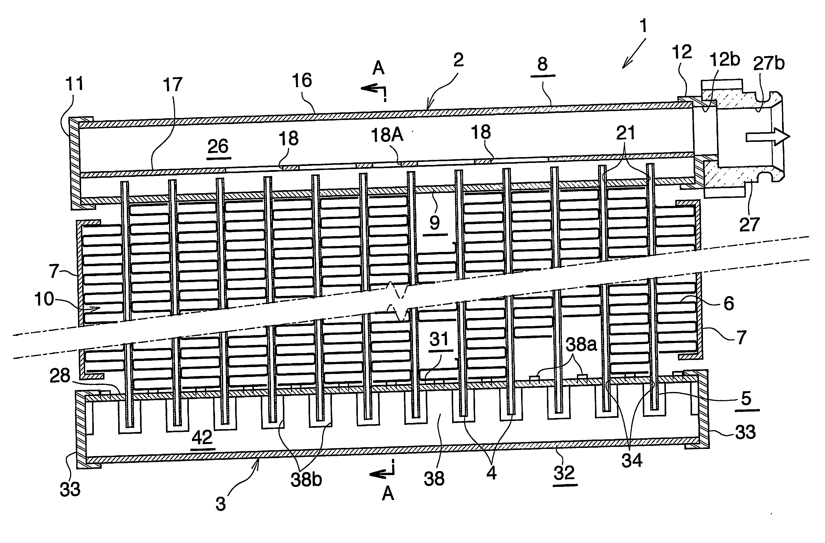
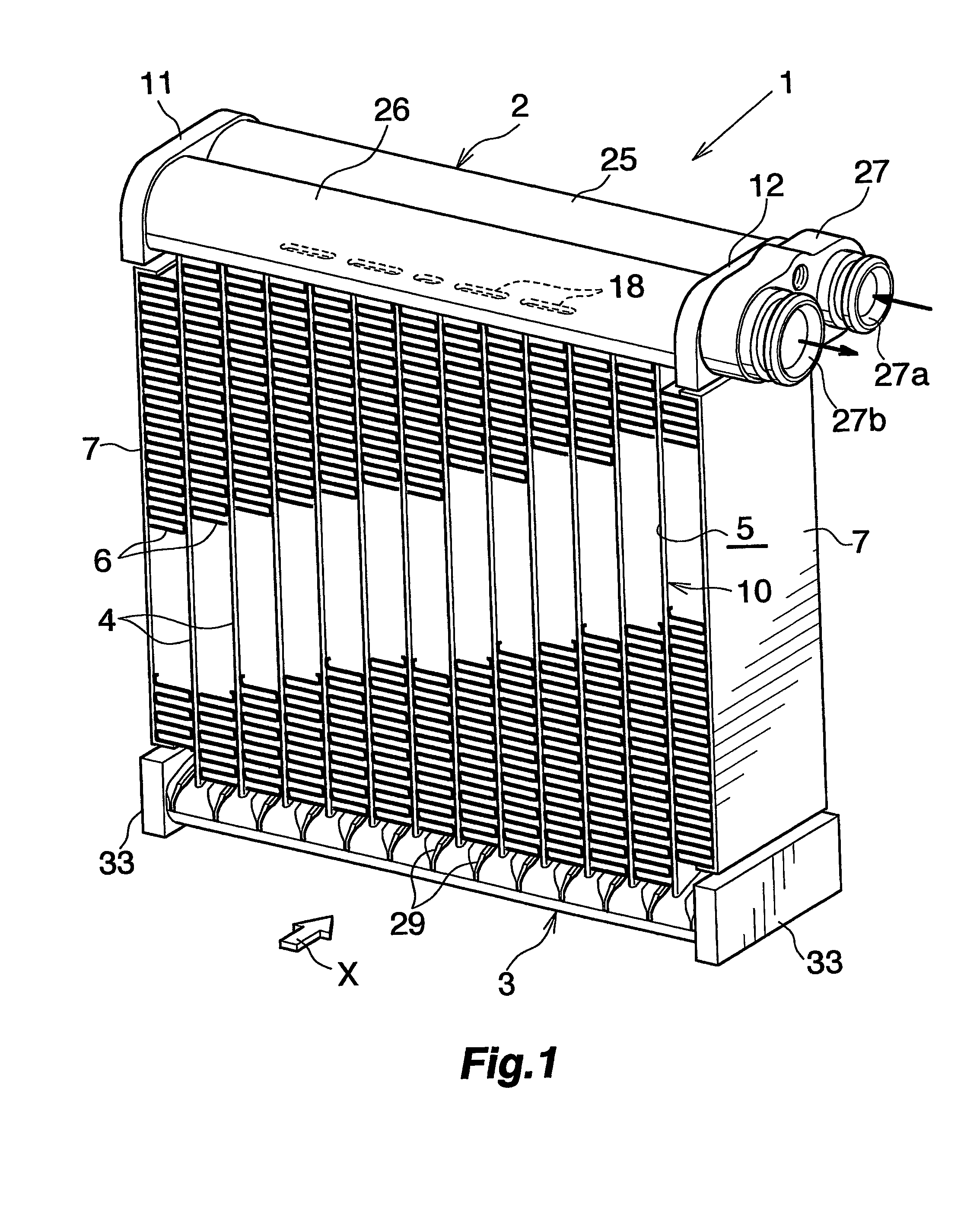
[0130] described, each of the grooves 29 has a flat bottom face, whereas this structure of grooves is not limitative. Each groove may have a bottom face shaped to a circular-arc cross section which is recessed toward a widthwise midportion of a bottom of the groove. Preferably, the bottom face of the groove is then given a radius of curvature which is ½ of the width of the bottom of the groove. In this case, the term the “depth of the groove 29” refers to the depth thereof at the midportion of the bottom.
[0131] Further according to the first embodiment described, each of the grooves 29 comprises first to third portions 29a to 29a, whereas this groove construction is not limitative; the groove may have a first portion 29a extending to the junction 3d of the top surface 3a and the front or rear side surface 3b, and a third portion 29c joined to the outer end of this portion 29a without having any second portion 29b. Stated more specifically, when seen in longitudinal section, the gro...
second embodiment
[0132]FIG. 10 shows the invention.
[0133] In the case of the embodiment of FIG. 10, the lower tank 3 has a horizontal flat top surface 3a. The lower tank 3 is provided, in each of the front and rear side portions thereof, with a plurality of grooves 29 extending from the midportion of the top surface 3a with respect to the forward or rearward direction toward the front or rear side surface 3b, comprising a first portion 29a, second portion 29b and third portion 29c, and arranged laterally at a spacing. Since the top surface 3a of the lower tank 3 is horizontal and flat, the upper member 31 is also different in shape from that of the first embodiment. With the exception of the above features, the second embodiment is the same as the first.
third embodiment
[0134]FIG. 11 shows the invention.
[0135] The embodiment of FIG. 11 has grooves 29 each comprising a first portion 29a-existing on the top surface 3a of the lower tank 3 and having a depth gradually increasing as the groove extends from the highest portion (28) side of the top surface 3a toward the front or rear side edge. Accordingly, the second portion 29b existing at the junction of the lower tank top surface 3a and each of the front and rear opposite side surfaces 3b has a shortened length. With the exception of this feature, the third embodiment is the same as the first.
[0136]FIG. 12 shows a fourth embodiment of the invention. With reference to FIG. 12, the junction 3d of the top surface 3a of the lower tank 3 and each of the front and rear opposite side surfaces 3b is provided with a plurality of grooves 50 arranged laterally at a spacing. Each groove 50 has a bottom face slanting downward as the groove extends forwardly or rearwardly outward. Thus, the junction 3d of the lowe...
PUM
 Abstract
Description
Claims
Application Information
 - R&D
- Intellectual Property
- Life Sciences
- Materials
- Tech Scout
- Unparalleled Data Quality
- Higher Quality Content
- 60% Fewer Hallucinations
Browse by: Latest US Patents, China's latest patents, Technical Efficacy Thesaurus, Application Domain, Technology Topic, Popular Technical Reports.
© 2025 PatSnap. All rights reserved.Legal|Privacy policy|Modern Slavery Act Transparency Statement|Sitemap|About US| Contact US: help@patsnap.com


