Liquid pressure transfer printing apparatus

a printing apparatus and liquid pressure technology, applied in printing presses, printing, printing, etc., can solve the problems of difficult effective application, remarkably increased fabrication cost or installation cost, and difficult to achieve, and achieves no increase in manufacturing cost, simple and easy constitution, and prevent the effect of residue deposition

Inactive Publication Date: 2006-07-27
TRINITY IND CORP
View PDF11 Cites 6 Cited by
  • Summary
  • Abstract
  • Description
  • Claims
  • Application Information

AI Technical Summary

Benefits of technology

[0012] Further, in a preferred embodiment, in which both of the gates are disposed movably along the longitudinal direction of the tank where the work enters into and exits from the tank, residues of the film not transferred to the work can be recovered while following after the movement of the work that enters into and exits from the tank thereby preventing deposition of the residues to the surface of the work.
[0013] Further, in another preferred embodiment, in which both of the gates are disposed such that they can advance and retract between a standby position completely submerged in the liquid in the tank and a suction position for sucking the residues, residues that can not be recovered completely by both of the gates can be flushed away by the stream at the liquid surface during standing of both of the gates in the liquid in the tank, and deposition of the contaminants by the residues to both of the gates can be prevented.
[0014] A further embodiment in which each of the gates comprises a slit nozzle having a suction port that opens slitwise along the lateral direction of the tank and connected with a suction hose for sucking the residues floating on the surface of the liquid in the tank from the suction port and discharging them to the outside of the tank—has an advantage of simple and easy constitution and with no increase for the manufacturing cost.
[0015] In a further embodiment in which both of the gates are arranged so as to correspond to one end and the other end of the film to suppress swelling and diffusion of the film caused by an activating agent upon coating the activating agent to the film that is cut into a predetermined size and supplied to the surface of the liquid in the tank, since the pattern printed on the film is clearly transferred to the surface of the work at a size approximate to the original size, it has an advantage capable of improving the transferred.
[0016] In a further preferred embodiment in which a pair of conveyors for transporting the film that is cut into a predetermined size and supplied to the surface of the liquid in the tank along the longitudinal direction of the tank are disposed along the right and left side walls of the tank, since the film can be moved reliably to the transfer position while suppressing the swelling of the film caused by the activating agent by the right and left side walls, this provides an advantage capable of improving the transfer quality and speeding up the production tact of the liquid pressure transfer printing to improve the production efficiency.
[0017] As described above, the present invention provides an effect capable of effectively recovering the residues of the film not transferred to the surface of the work but remained on the surface of the liquid in the tank thereby capable of reliably preventing seeds from resulting in the surface of the work.

Problems solved by technology

However, since a highly skilled technique is necessary for the clear coating of applying a uniform surface protective coating entirely to a work to be applied with transfer printing having various three dimensional shapes, for example, in interior parts or external parts of automobiles and a complicate control is necessary for coating apparatus that automatically conducts such painting operation, it involves a problem that the fabrication cost or installation cost remarkably increases in order to apply the top coating.
However, since it is difficult to effectively remove the residues of the film floating on the surface of liquid in the tank merely by the means described above, in a case where of intending to speed up the production tact of the liquid pressure transfer printing, thereby improving the production efficiency, residues of the film not transferred to a succeeding work may possibly be deposited to the surface of the work to form seeds on the surface of the work.

Method used


Image

  • Liquid pressure transfer printing apparatus
  • Liquid pressure transfer printing apparatus
  • Liquid pressure transfer printing apparatus

Examples


Embodiment Construction

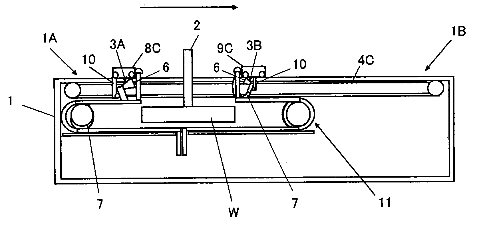
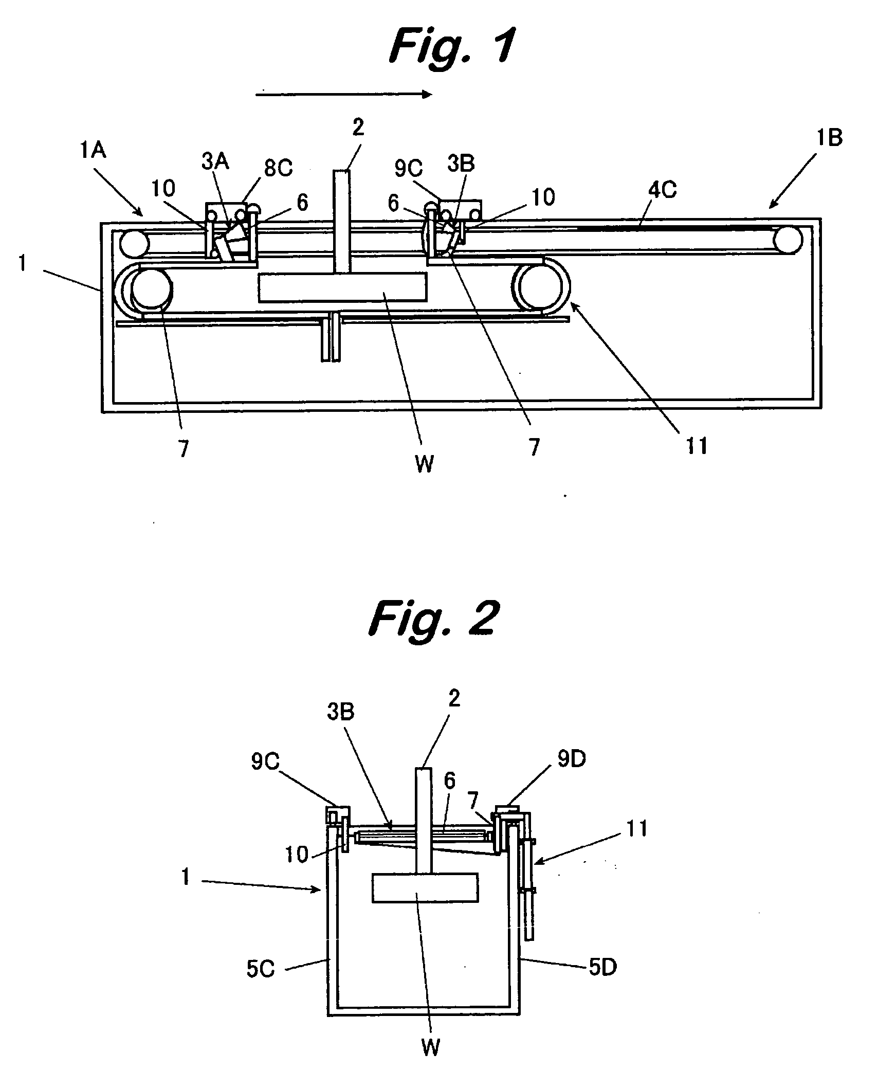
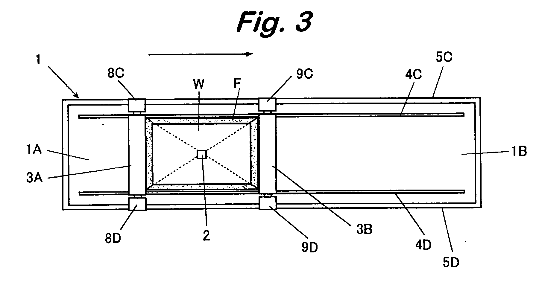
[0024] In the drawings, are shown tank 1 for liquid pressure transfer printing (hereinafter also sometimes referred to as a tank), a work W to be applied with transfer printing under liquid pressure (hereinafter also sometimes referred to as a work) which enters into and exits from the tank 1 being suspended from a transportation jig 12, a film for applying liquid pressure transfer printing (hereinafter also sometimes referred to as a film) cut to a predetermined size and supplied to the surface of the liquid in the tank 1, a pair of gates 3A and 3B for sucking residues of the film F floating on the surface of the liquid in the tank 1 from both of the inlet side 1A and the exit side 1B of the tank 1 where the work W enters into and discharging the residues out of the tank 1, and a pair of chain conveyors 4C and 4D for transporting the film F cut into a predetermined size and supplied to surface of the liquid in the tank 1 from the inlet side 1A to the exit side 1B along the longitud...


PUM

PropertyMeasurementUnit
swellingaaaaaaaaaa
sizeaaaaaaaaaa
pressureaaaaaaaaaa

Abstract

A liquid pressure transfer printing apparatus in which a work to be applied with transfer printing is urged onto a film for applying liquid pressure transfer printing supplied to the surface of a liquid in a tank for liquid pressure transfer printing to submerge the film into the liquid comprises a pair of gates each having a suction mechanism for sucking residues not transferred to the submerged work but remained on the surface of the liquid in the tank from the inlet side and the exit side of the tank while the work W is submerged in the liquid, thereby capable of preventing the residues of the film remained on the surface of the liquid in the tank not transferred to the surface of the work from depositing to the surface of the work and forming seeds.

Description

BACKGROUND OF THE INVENTION [0001] 1. Field of the Invention [0002] The present invention concerns a liquid pressure transfer printing apparatus of urging a work to be applied with transfer printing onto a film for applying liquid pressure transfer printing supplied to the surface of water in a tank for liquid pressure transfer printing to submerge the film into water and, more in particular, it relates to a liquid pressure transfer printing apparatus which is suitable to a case, for example, of using a multi-layered film, as a film for applying liquid pressure transfer printing, in which a curable resin layer to form a surface protective coating by being cured under irradiation of actinic energy rays such as UV-rays or by heating is interposed between a film soluble to water or like other aqueous solution and a pattern print layer. [0003] 2. Statement of the Related Art [0004] Generally, in a work to be applied with a pattern by liquid pressure transfer printing, a liquid soluble f...

Claims


Application Information

Patent Timeline
Patent Type & Authority Applications(United States)
IPC IPC(8): B41D7/00
CPCB41F16/008B44C1/1758
Inventor YAMAMORI, MASATOTSUJIMOTO, SHINYA
Owner TRINITY IND CORP
Why Eureka
Try Eureka