Valve control device reducing noise

a control device and valve technology, applied in the direction of electric control, machines/engines, mechanical equipment, etc., can solve the problems of increasing annoyance for vehicle occupants, noise will be caused, etc., and achieve the effect of reducing noise, driving speed of valves, and reducing valve driving speed

Active Publication Date: 2006-07-27
DENSO CORP +1
View PDF2 Cites 0 Cited by
  • Summary
  • Abstract
  • Description
  • Claims
  • Application Information

AI Technical Summary

Benefits of technology

[0008] It is therefore an object of the present invention to provide a control device of a valve located in a fluid passage for performing air supply or gas exhaust with an engine, the control device reducing annoyance due to a noise caused by deposit elimination operation.
[0010] Thus, the driving pattern such as driving speed or a driving range of the valve is changed in accordance with the engine state quantity such as engine rotation speed that affects engine sound. The driving speed of the valve is reduced to reduce a noise accompanying the deposit elimination operation when the engine rotation speed is low and the engine sound is low. The driving speed of the valve is increased to shorten a deposit elimination period when the engine sound is high and the noise accompanying the deposit elimination operation is less audible. As a result, annoyance due to a noise accompanying the deposit elimination operation can be reduced.

Problems solved by technology

As a result, a noise will be caused.
Therefore, the noise accompanying the deposit elimination operation reaches vehicle occupants and increases annoyance for the vehicle occupants.

Method used


Image

  • Valve control device reducing noise
  • Valve control device reducing noise
  • Valve control device reducing noise

Examples


first embodiment

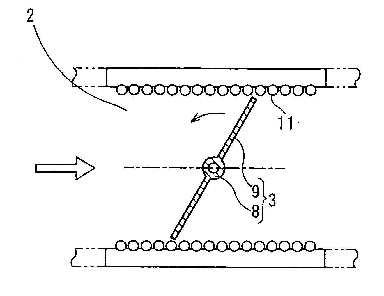
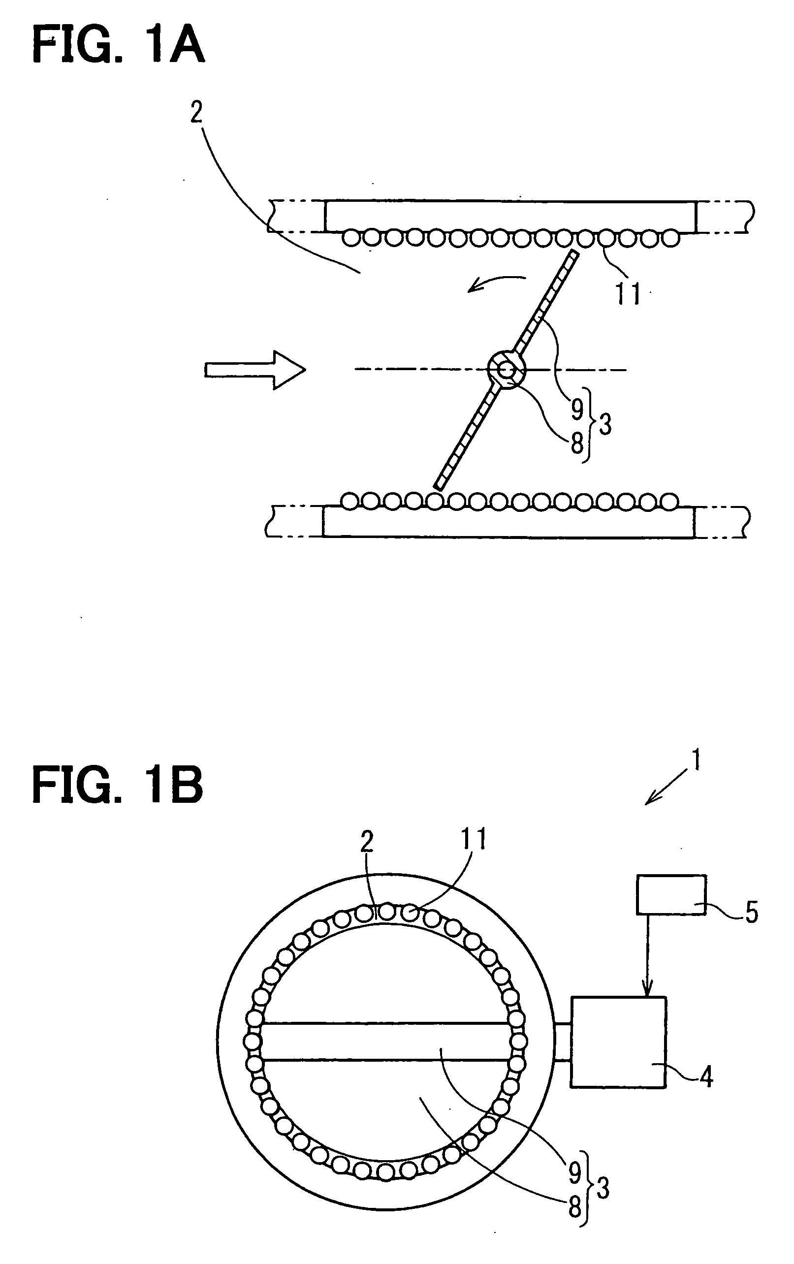
[0023] Referring to FIGS. 1A and 1B, a valve control device 1 according to the present invention is illustrated. The valve control device 1 drives and controls a valve 3 such as a throttle valve, an exhaust gas recirculation valve (EGR valve) or an exhaust gas restriction valve located in a fluid passage 2, through which a fluid taken or discharged by an engine passes.

[0024] The valve control device 1 is installed to the fluid passage 2 that performs air intake or gas exhaust with the engine. The valve control device 1 has the valve 3, an electric motor 4, and an electronic control unit (ECU) 5. The valve 3 regulates a flow rate of the intake air or exhaust gas. The electric motor 4 is an actuator that drives the valve 3. The ECU 5 operates as a controller that drives and controls the valve 3 by controlling the operation of the electric motor 4.

[0025] For example, the valve 3 is a butterfly valve having a shaft portion 8 connected to a rotary shaft (not shown) of the electric motor...

second embodiment

[0039] Referring to FIG. 5, a control mode of a valve control device 1 according to the present invention is illustrated. As shown in FIG. 5, the cleaning mode and the cleaning opening degree pattern are divided in two steps. The cleaning mode is divided into a first step in which the engine rotation speed RPM decreases to zero after the start of the engine stop and a second step in which the engine rotation speed RPM is zero. In this embodiment, the opening degree change rate and a driving range (opening degree amplitude) of the valve 3 during the elimination of the deposit 11 are selected from the driving patterns, and are corrected in accordance with the engine rotation speed.

[0040] The opening degree amplitude of the second step is set smaller than that of the first step. More specifically, the opening degree amplitude at the time when the engine rotation speed is zero is set smaller than the opening degree amplitude at the time when the engine rotation speed is greater than zer...

third embodiment

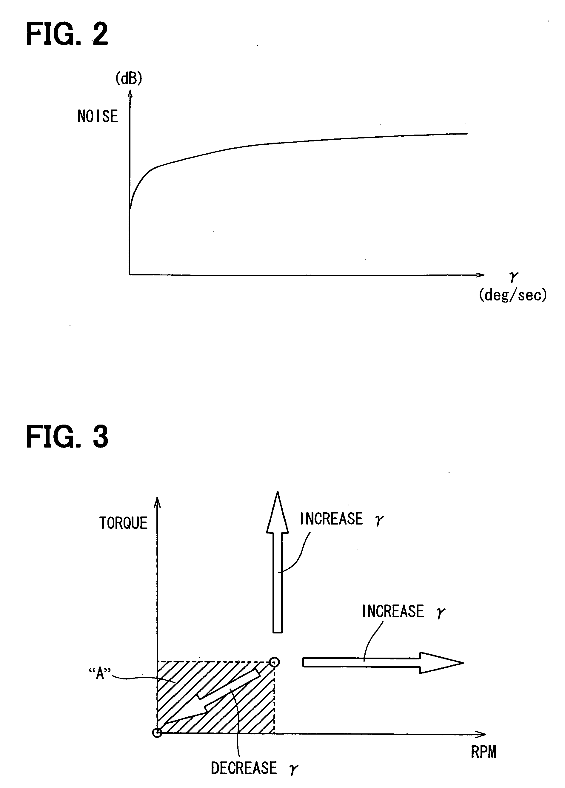
[0043] Referring to FIG. 6, a control mode performed by a valve control device 1 according to the present invention is illustrated. The valve control device 1 of this embodiment changes the valve opening degree change rate and the opening degree amplitude of the valve 3 in accordance with the engine rotation speed RPM when the elimination of the deposit 11 is performed. Even after the control mode is switched to the cleaning mode, the engine rotation speed RPM is monitored, and the opening degree change rate and the opening degree amplitude are corrected in accordance with the engine rotation speed RPM. Thus, in the cleaning opening degree pattern of this embodiment, both of the opening degree change rate and the opening degree amplitude are corrected to gradually decrease in accordance with the engine rotation speed RPM as shown in FIG. 6. As a result, the annoyance due to the noise accompanying the elimination of the deposit 11 can be further reduced when the engine rotation speed...


PUM


Abstract

A valve control device corrects a change rate of an opening degree of a valve in accordance with engine rotation speed when deposit elimination operation is performed. The valve control device corrects an inclination between a positive maximum opening degree and a negative maximum opening degree of the valve in accordance with the engine rotation speed when the deposit elimination operation is performed. Thus, when the engine rotation speed is low and a noise accompanying the deposit elimination operation becomes more audible, the change rate of the opening degree of the valve is reduced. As a result, the noise accompanying the deposit elimination operation is reduced and annoyance for vehicle occupants is reduced.

Description

CROSS REFERENCE TO RELATED APPLICATION [0001] This application is based on and incorporates herein by reference Japanese Patent Application No. 2005-18037 filed on Jan. 26, 2005 and Japanese Patent Application No. 2005-314252 filed on Oct. 28, 2005. BACKGROUND OF THE INVENTION [0002] 1. Field of the Invention [0003] The present invention relates to a control device of a valve such as a throttle valve or an exhaust gas recirculation valve (EGR valve) installed in a fluid passage for performing air supply or gas exhaust with an engine. [0004] 2. Description of Related Art [0005] A control device of a valve such as a throttle valve or an exhaust gas recirculation valve (EGR valve) installed in a fluid passage for performing air supply or gas exhaust with an engine performs deposit elimination operation with the valve in order to prevent malfunction due to deposits such as oil mist or soot adhering to a wall of the fluid passage. [0006] The deposit elimination operation by the valve is ...

Claims


Application Information

Patent Timeline
Patent Type & Authority Applications(United States)
IPC IPC(8): F02M25/07F02D11/10
CPCF02D11/10F02D41/0055F02M25/0701F02M25/0702Y02T10/47F02M26/50F02M26/49Y02T10/40
Inventor TAKEMOTO, EIJIKATSUNO, MASATOFUJITA, TATSUYANANBA, KUNIONAKAYAMA, YOSHINORI
Owner DENSO CORP
Why Eureka
Try Eureka