Simulation method for four-rotor aircraft
A quadrotor aircraft and flight state technology, applied in instruments, simulators, electrical testing/monitoring, etc., can solve problems such as complex connections, low model accuracy, and large-scale hardware-in-the-loop simulation systems
- Summary
- Abstract
- Description
- Claims
- Application Information
AI Technical Summary
Problems solved by technology
Method used
Image
Examples
specific Embodiment approach 1
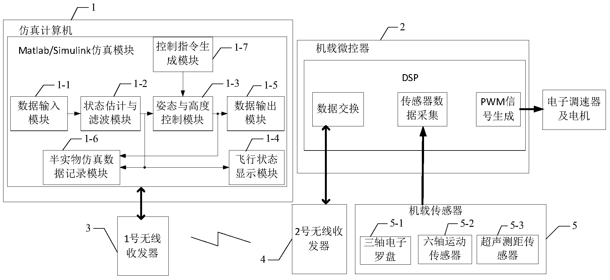
[0072] Specific implementation mode one: see figure 1 Illustrate the present embodiment, the semi-physical simulation method of quadrotor aircraft described in the present embodiment, it is realized based on following device, and this device comprises simulation computer 1, airborne microcontroller 2, No. 1 wireless transceiver 3,2 No. wireless transceiver 4 and airborne sensor 5;
[0073] The data signal input end of the airborne microcontroller 2 is connected with the data signal output end of the airborne sensor 5, the communication end of the airborne microcontroller 2 is connected with the signal input and output ends of the No. 2 wireless transceiver 4, and the No. 2 wireless transceiver The device 4 carries out data transmission with the No. 1 wireless transceiver 3 by way of wireless communication, and the signal input and output terminals of the No. 1 wireless transceiver 3 are connected with the signal input and output terminals of the simulation computer 1,
[0074...
specific Embodiment approach 2
[0081] Embodiment 2: The difference between this embodiment and the semi-physical simulation method for quadrotor aircraft described in Embodiment 1 is that the airborne sensor 5 includes a three-axis electronic compass 5-1 and a six-axis motion sensor 5-2. and ultrasonic ranging sensor 5-3,
[0082] The three-axis electronic compass 5-1 is used to collect three-axis magnetic induction intensity signals,
[0083] The six-axis motion sensor 5-2 is used to collect three-axis acceleration readings and three-axis orientation readings,
[0084] The ultrasonic ranging sensor 5-3 is used to collect ranging readings.
specific Embodiment approach 3
[0085] Specific embodiment three: The difference between this embodiment and the semi-physical simulation method of the quadrotor aircraft described in the second specific embodiment is that the described three-axis electronic compass 5-1 is implemented by an integrated circuit model HMC5883L, and the six-axis motion The model of the sensor 5-2 is implemented by an integrated circuit of MPU6050, and the ultrasonic ranging sensor 5-3 is realized by an integrated circuit of the model US-100.
PUM
 Abstract
Description
Claims
Application Information
 - R&D
- Intellectual Property
- Life Sciences
- Materials
- Tech Scout
- Unparalleled Data Quality
- Higher Quality Content
- 60% Fewer Hallucinations
Browse by: Latest US Patents, China's latest patents, Technical Efficacy Thesaurus, Application Domain, Technology Topic, Popular Technical Reports.
© 2025 PatSnap. All rights reserved.Legal|Privacy policy|Modern Slavery Act Transparency Statement|Sitemap|About US| Contact US: help@patsnap.com


