Structure of radiator

Inactive Publication Date: 2006-07-27
HUANG WEI CHENG +1
View PDF10 Cites 7 Cited by
  • Summary
  • Abstract
  • Description
  • Claims
  • Application Information

AI Technical Summary

Benefits of technology

[0007] Based on these observations, to achieve an excellent effect of thermal dissipation, the present invention introduces a radiator in which an inner cylinder and an outer cylinder are correspondingly sheathed, and appropriate space is kept between inner cylinder and outer cylinder to allow the flow of liquid. A spiral guide is in

Problems solved by technology

In accordance with the advance of main unit's operation speed, the thermal generated by chips becomes a problem.
Therefore, the technology of thermal dissipation becomes an important issue.
As the existing technology of air cooled thermal dissipation is unable to meet the requirement of thermal dissipation.
To achieve a bett

Method used


Image

  • Structure of radiator
  • Structure of radiator
  • Structure of radiator

Examples


Embodiment Construction

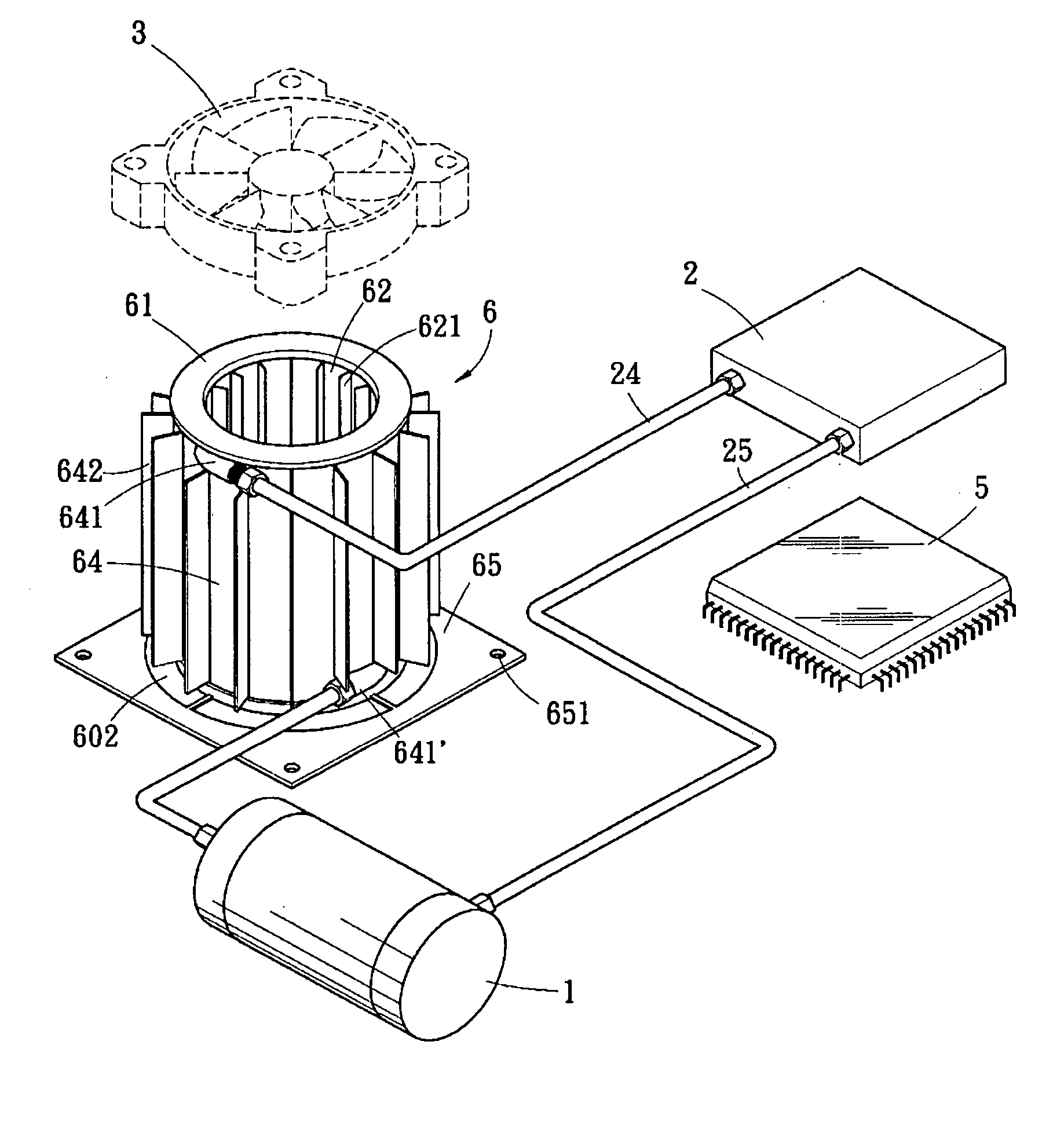
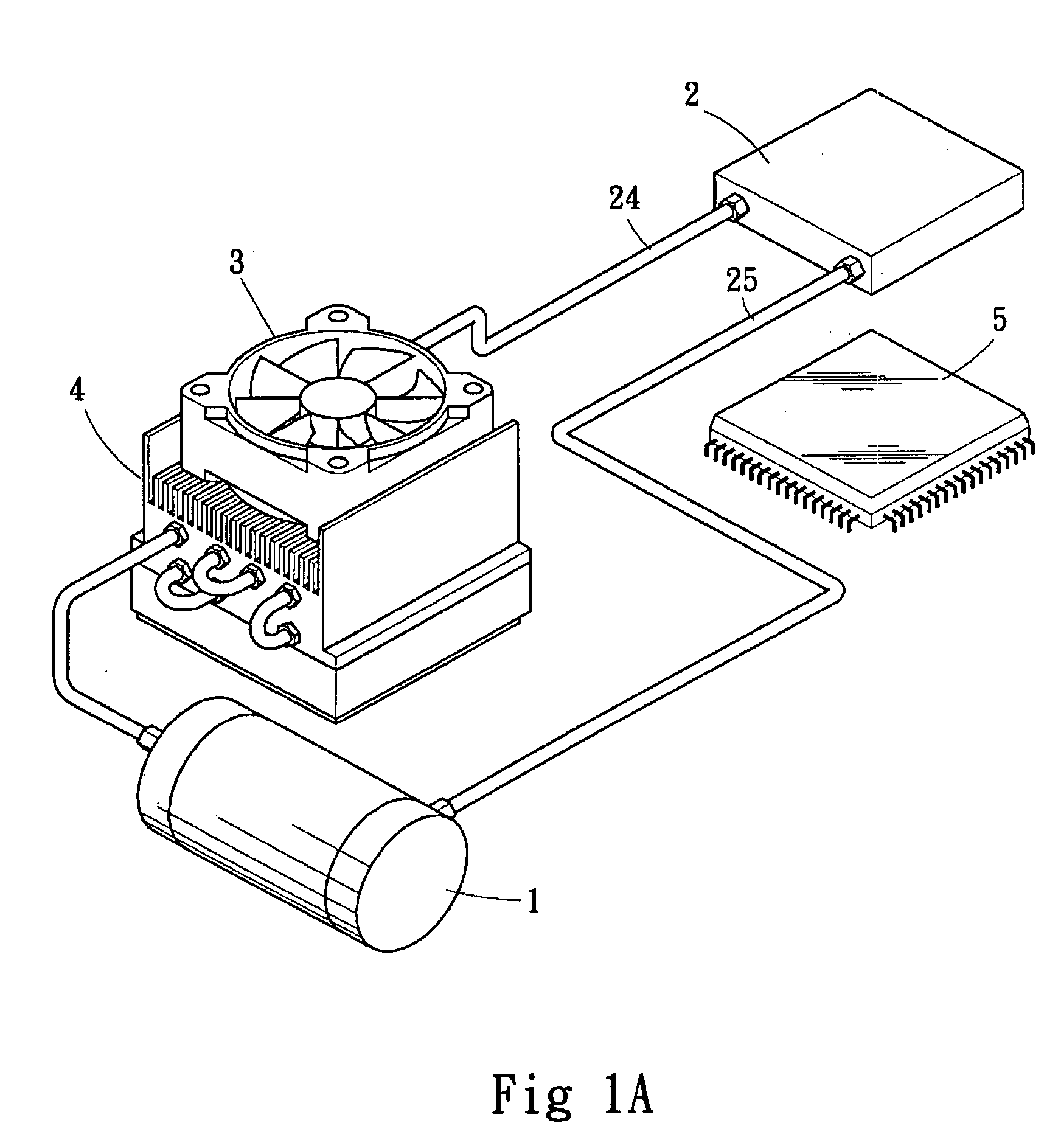
[0026] Referring to FIGS. 2 and 3, the liquid cooled thermal dissipation system is composed of a pump 1, a waterblock 2, a fan 3, a radiator 6, as well as input and output pipes 24, 25, in which the waterblock 2 is attached to the operating chip 5, while liquid is delivered by pump 1 through input and output pipes 24, 25 to the radiator 6 according to the present invention to realize a complete circulation, and a fan 3 is installed on the top of radiator 6 to enforce the efficiency of thermal dissipation.

[0027] The radiator 6 according to the present invention is composed of a pair of inner, outer cylinders 62, 64, a spiral guide 63, an upper cover 61, and a lower base 65. The upper cover 61 is covered on the top of inner, outer cylinders 62, 64, while the lower base 65 is installed at the bottom of inner, outer cylinders 62, 64 for packaging, where an appropriate space 60 between the inner, outer cylinders 62, 64 is reserved, as shown in FIG. 4A, to allow the liquid flow, and two ...


PUM


Abstract

The present invention is a structure of radiator. More specifically, it is a radiator in which an inner cylinder and an outer cylinder are correspondingly sheathed, and appropriate space is kept between inner cylinder and an outer cylinder to accept the flow of liquid. A spiral guide is installed inside the said space to guide the continuous flow of liquid in spiral channel. Further, at the inside wall of inner cylinder and outside wall of outer cylinder, multiple dissipation fins are formed. Through the enforced thermal dissipation of an additional fan installed atop, the radiator can accordingly perform an excellent effect of thermal dissipation.

Description

BACKGROUND OF THE INVENTION [0001] 1) Field of the Invention [0002] This invention is a structure of radiator. More specifically, it is used in a liquid cooled thermal dissipation system of computer's main unit to perform thermal exchange, such that the size of whole radiator is scaled down while the efficiency of radiator for thermal dissipation is enhanced. [0003] 2) Description of the Prior Art [0004] Computer technologies have been developed fast recently. In accordance with the advance of main unit's operation speed, the thermal generated by chips becomes a problem. Therefore, the technology of thermal dissipation becomes an important issue. As the existing technology of air cooled thermal dissipation is unable to meet the requirement of thermal dissipation. Diverse liquid cooled thermal dissipation systems are emerging accordingly. [0005] A conventional liquid cooled thermal dissipation system is shown in FIG. 1A. The modules constructing a liquid cooled thermal dissipation sy...

Claims


Application Information

Patent Timeline
IPC IPC(8): H05K7/20
CPCH01L23/467H01L23/473H01L2924/0002H01L2924/00
Inventor HUANG, WEI-CHENGHSU, SUNG-LIN
Owner HUANG WEI CHENG
Why Eureka
Try Eureka