
Hydraulic vehicle jack system

Inactive Publication Date: 2006-07-27
COENEN DUANE +1
View PDF10 Cites 54 Cited by
  • Summary
  • Abstract
  • Description
  • Claims
  • Application Information

AI Technical Summary

Benefits of technology

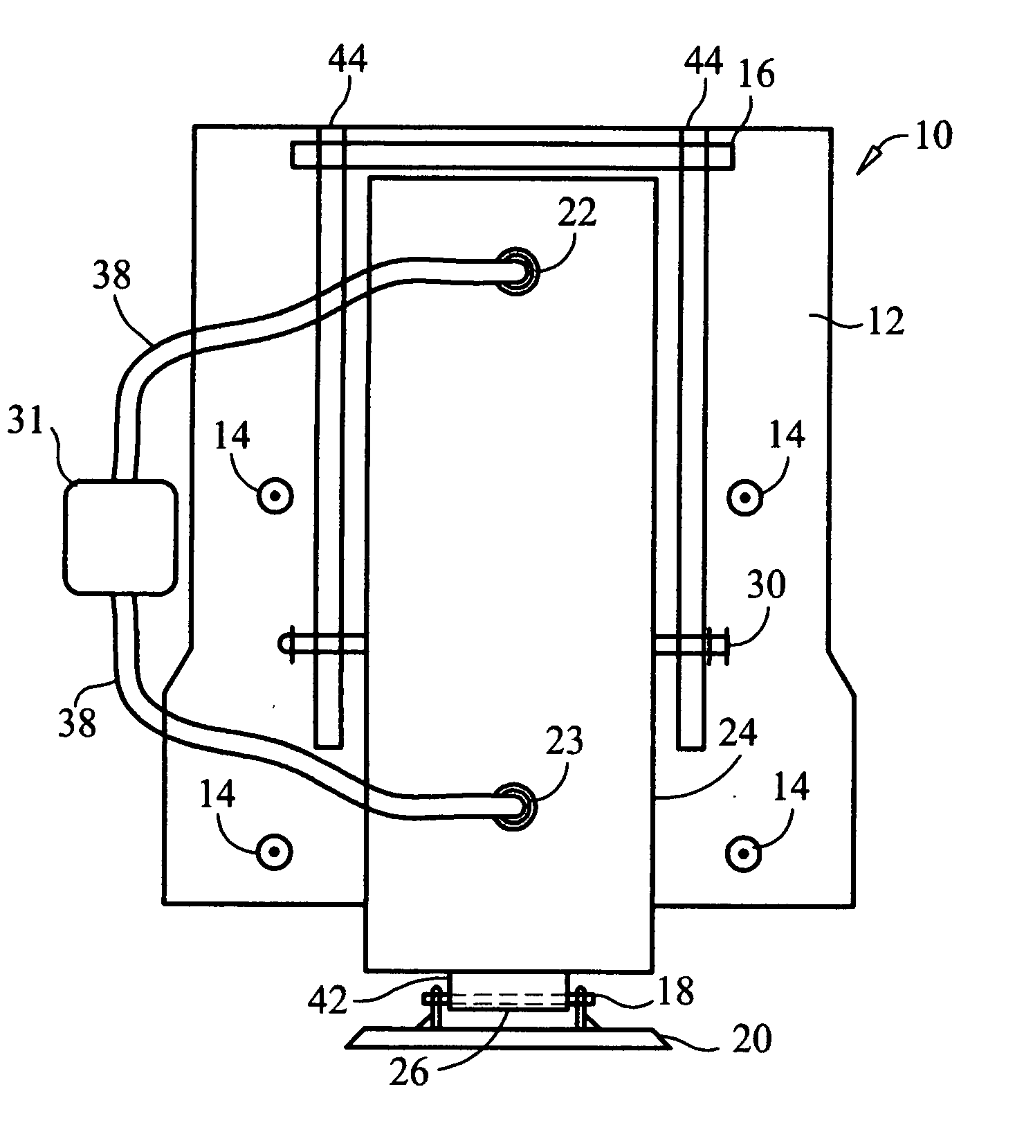
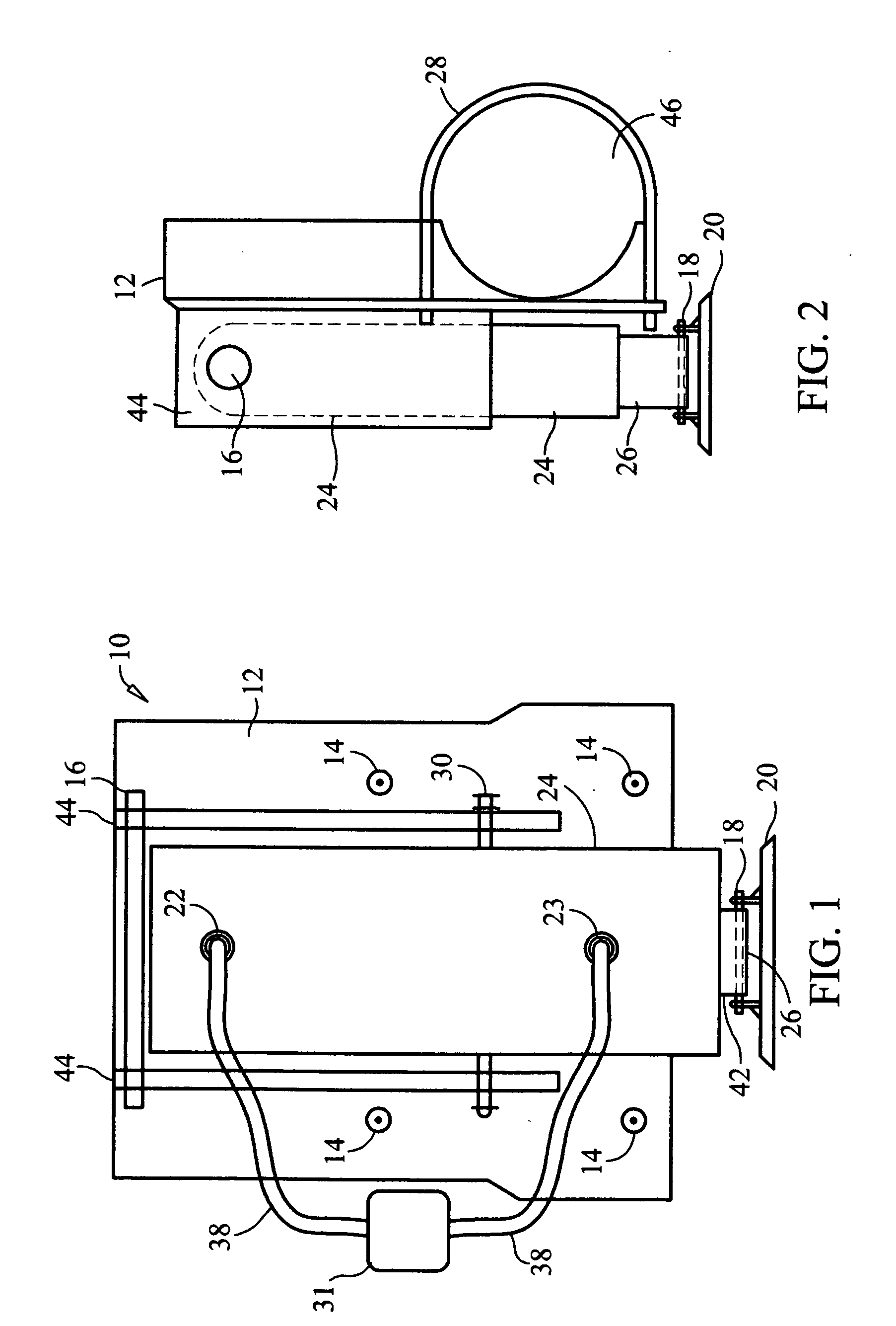
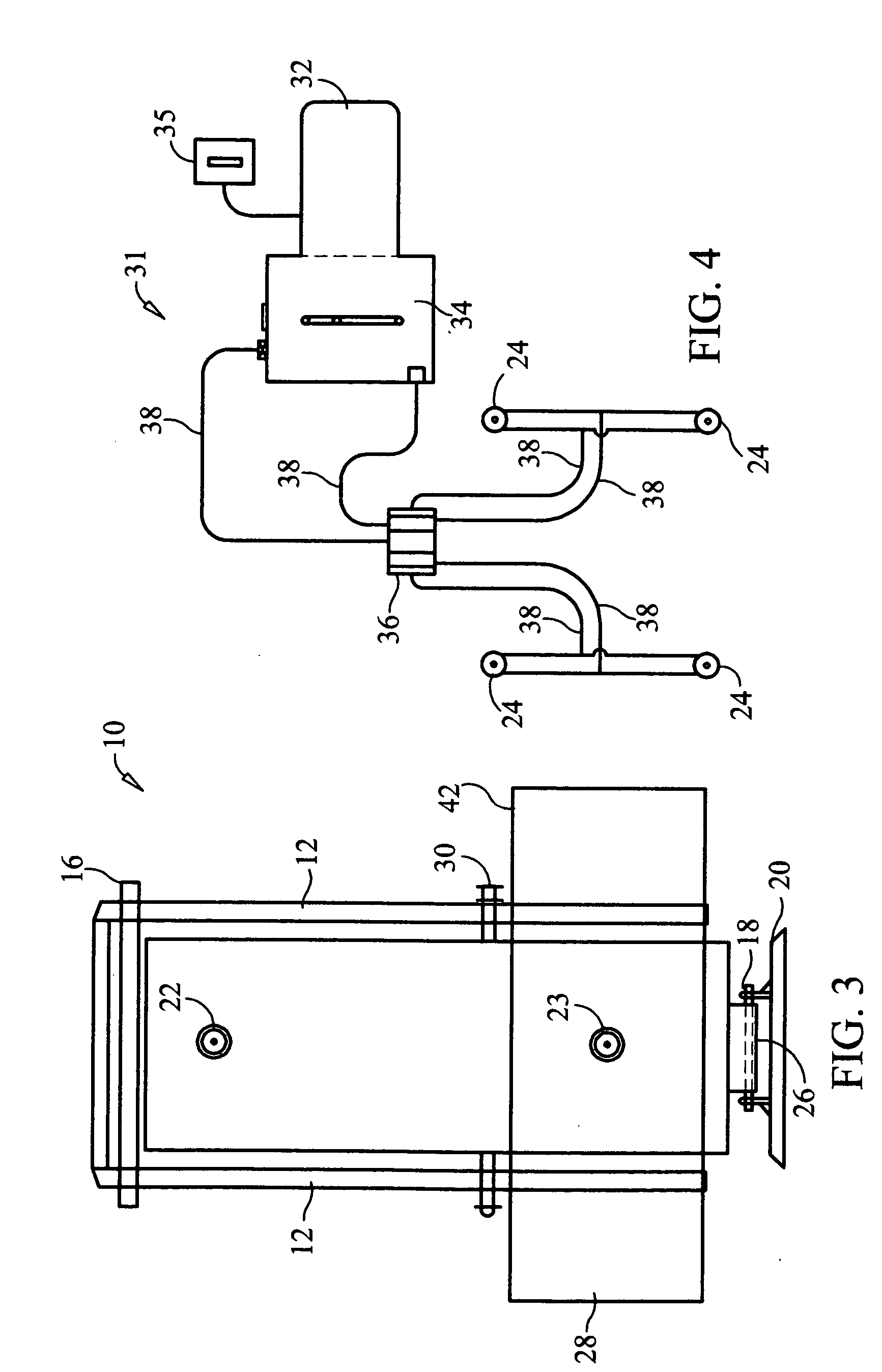
[0010] The present invention addresses the foregoing problems by eliminating the use of moving mechanical parts and the need for power from the vehicle to be supplied to the jack. Thus, the hydraulic vehicle jack system is a device that is safer when used, requires less maintenance, and facilitates easier repairs. The hydraulic vehicle jack system comprises a hydraulic vehicle jack mounted to the chassis of a vehicle near one of its wheels, a hydraulic pump system to provide pressurized fluid to the hydraulic vehicle jack, and a control device to activate the hydraulic pump system.
[0012] The hydraulic pump system is comprised of a pump, a fluid reservoir connected to the pump, a valve connected to the pump and fluid reservoir, and a plurality of hydraulic lines emanating from the valve. The lines are connected to ports formed in the outer cylinder of the hydraulic vehicle jack and supply hydraulic fluid to the vehicle jack. The pump system, preferably powered by a source independent of the vehicle, is integrated into the vehicle where it can be operated safely.
[0013] To operate the hydraulic vehicle jack, the control device, preferably a keyed unit in a location easily accessible to the vehicle's driver, activates the hydraulic pump system. The pump system sends pressurized fluid, preferably an oil, to the outer cylinder of the jack. As the outer cylinder fills with fluid, the inner piston rod extends vertically and raises the vehicle off the ground. All this achieved without the use of gears, cranks or belts; thus, eliminating mechanical moving parts and increasing the safety of the device.

Problems solved by technology

Once the jack is removed, users that are not familiar with the jack may find it difficult to position beneath the vehicle and operate the jack.
Often, the inexperienced or unfamiliar user may need to consult the jack's instruction manual.
However, much of the prior art uses the vehicle as the source of power for operating the jack.
In addition, many of the prior art jacks rely on moving mechanical parts.

Method used


Image

  • Hydraulic vehicle jack system
  • Hydraulic vehicle jack system
  • Hydraulic vehicle jack system

Examples


Embodiment Construction

[0019] In the following detailed description, reference is made to the accompanying drawings that form a part hereof, and in which is shown by way of illustration, specific embodiments in which the invention may be practiced. These embodiments are described in sufficient detail to enable those skilled in the art to practice the invention, and it is to be understood that other embodiments may be utilized. It is also to be understood that structural, procedural and system changes may be made without departing from the spirit and scope of the present invention. The following detailed description is, therefore, not to be taken in a limiting sense, and the scope of the present invention is defined by the appended claims and their equivalents. For clarity of exposition, like features shown in the accompanying drawings are indicated with like reference numerals and similar features as shown in alternate embodiments in the drawings are indicated with similar reference numerals.

[0020] Refer...


PUM


Abstract

A hydraulic vehicle jack system that safely lifts vehicles without using the vehicle as a power source power source and without moving mechanical parts. The system comprises: (a) a hydraulic vehicle jack mounted to the chassis of a vehicle near one of its wheels; (b) a hydraulic pump system to provide pressurized fluid to the hydraulic vehicle jack; and (c) a control device to activate the hydraulic pump system. Also disclosed is a method for lifting a vehicle.

Description

[0001] This application claims the benefit of U.S. Provisional Application No. 60 / 647,480, filed Jan. 27, 2005, which is incorporated herein by reference.BACKGROUND OF INVENTION [0002] 1. Technical Field [0003] The present invention relates generally to jack systems for lifting vehicles and, more particularly, to a hydraulic vehicle jack system that safely lifts vehicles without using the vehicle as a power source and without moving mechanical parts. [0004] 2. Description of Related Art [0005] Jacks are used to raise a variety of vehicles such as automobiles and trucks from the ground. Most commonly, these devices are used when the vehicle must be lifted to repair or perform maintenance upon it. For example, a portion of an automobile must be raised in order to change a tire. [0006] Many of these jacks are stowed in the vehicle, usually in the trunk. To remove the jack, the user is typically required to remove various items from the trunk first. Once the jack is removed, users that ...

Claims


Application Information

Patent Timeline
IPC IPC(8): B60S9/02
CPCB60S9/12
Inventor COENEN, DUANEKASTER, BRIAN
Owner COENEN DUANE
Learn More