Segment connection type electric rotating machine

a technology of electric rotating machines and segments, applied in the direction of windings, dynamo-electric components, supports/encloses/casings, etc., can solve the problems of motor assembly work, deformation of neutral point connecting leads, and large outside dimensions of the outer dimension of the machine, and achieve the effect of easy bending

Inactive Publication Date: 2006-07-27
DENSO CORP
View PDF13 Cites 37 Cited by
  • Summary
  • Abstract
  • Description
  • Claims
  • Application Information

AI Technical Summary

Benefits of technology

[0035] The present invention makes it possible to use a wire having any shape of cross section (round wire, for example) which is easy to bend compared to a rectangular wire as the power supply lead. Accordingly,

Problems solved by technology

The electric rotating machine having the segment connection type stator coil disclosed in Japanese Patent Application Laid-open No. 2003-348780 has a problem in that the outer dimension thereof becomes large, because, in this electric rotating machine, the neutral point connecting lead is taken from the outermost conductor holding space, and the power supply lead is laid between the outermost conductor holding space and a connector disposed on a radially inner side of the stator along the head-side coil ends.
In addition, the electric rotating machines disclosed in Japanese Patent Applications Laid-open No. 2003-348780 and Laid-open No. 2000-166149 have a problem in that the neutral point connecting lead may deform to thereby come into contact with the rotor when the neut

Method used


Image

  • Segment connection type electric rotating machine
  • Segment connection type electric rotating machine
  • Segment connection type electric rotating machine

Examples


Embodiment Construction

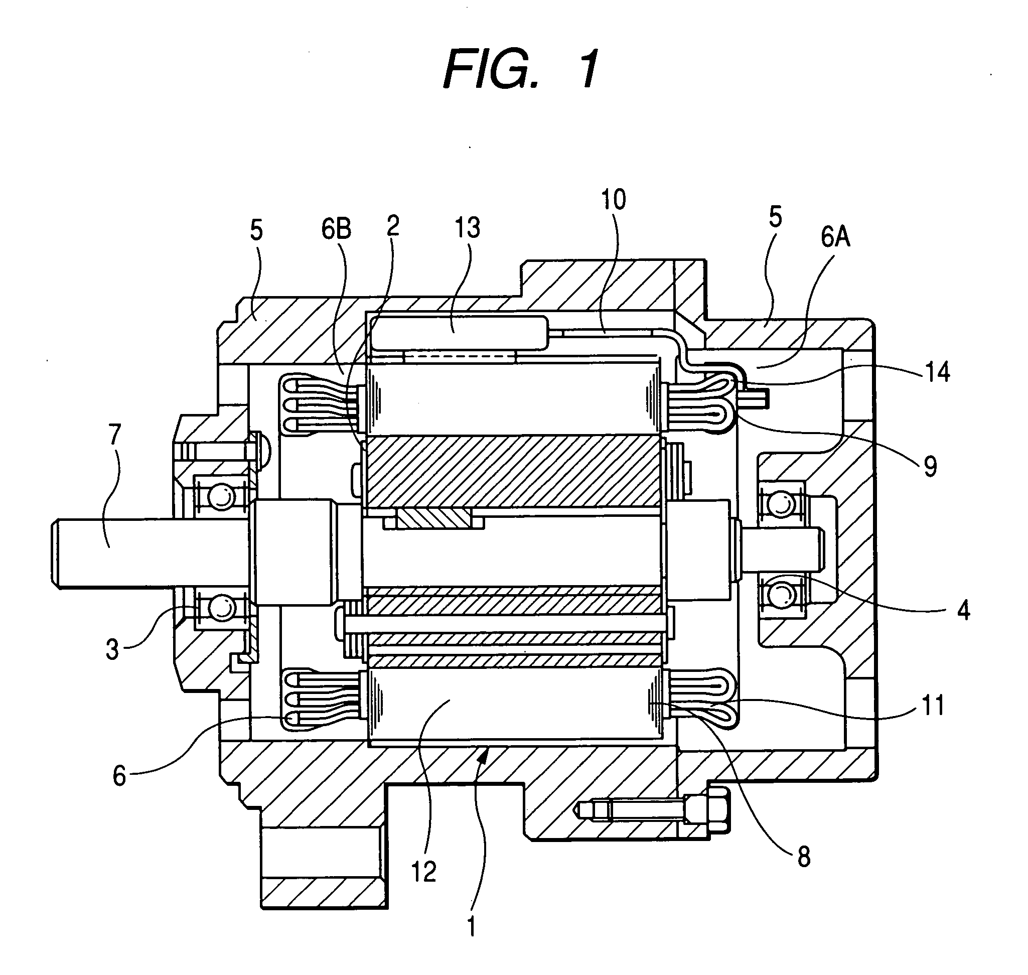
[0044]FIG. 1 is an axial cross-sectional view of a segment connection type electric rotating machine usable as a motor for driving a vehicle wheel according to a first embodiment of the invention.

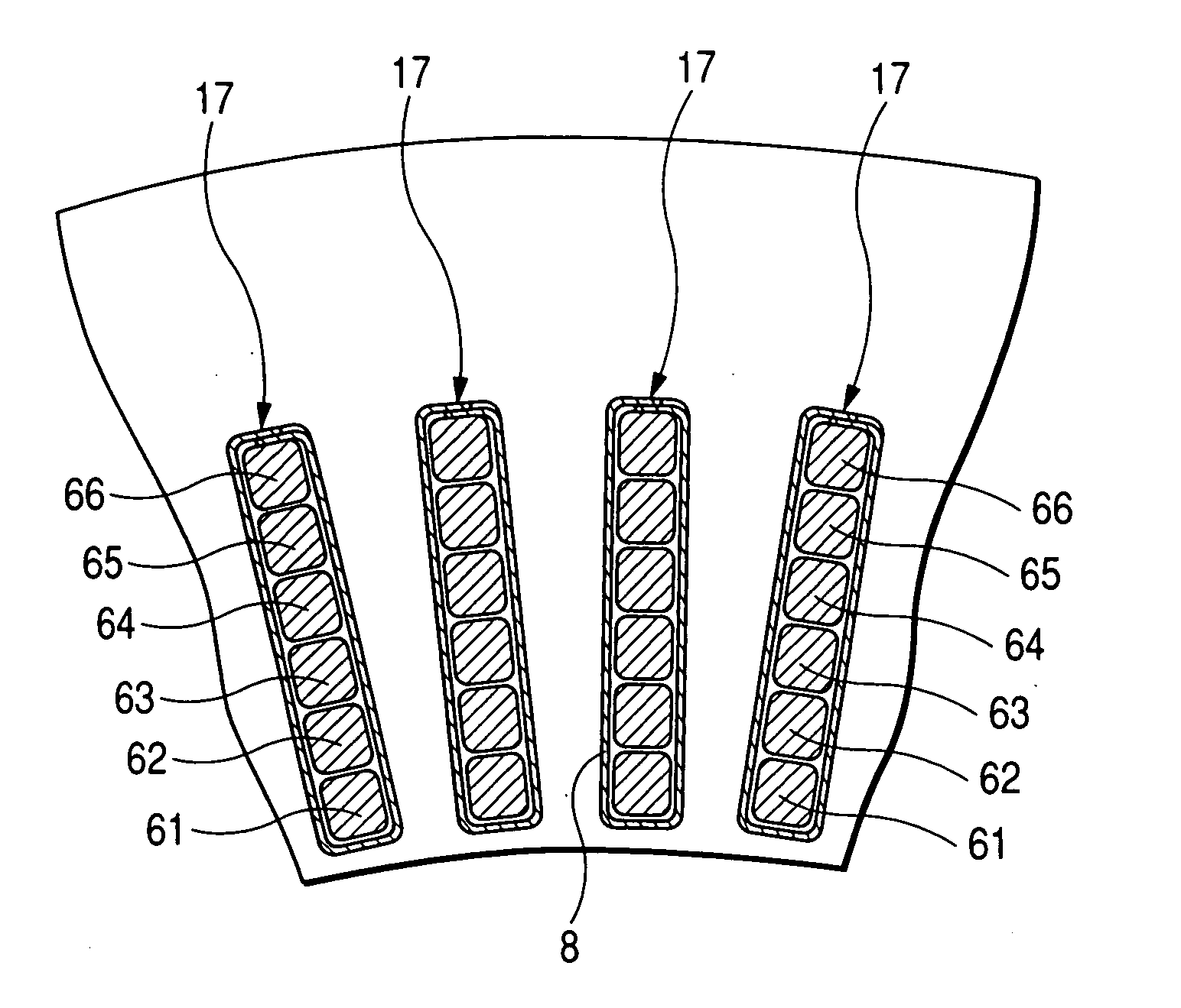
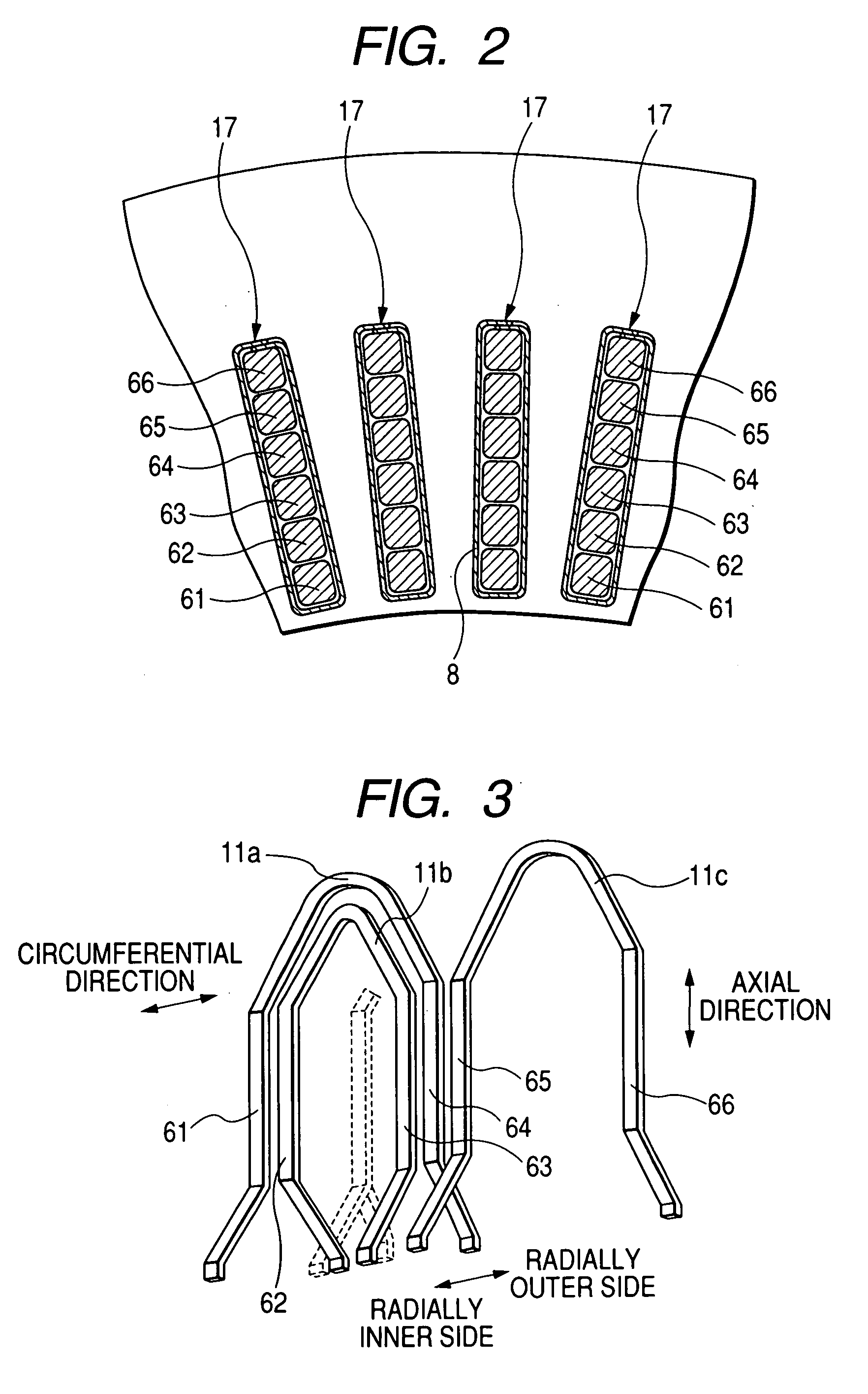
[0045] In FIG. 1, the reference numeral 1 denotes a stator, 2 denotes a rotor, 3 denotes a front bearing, 4 denotes a rear bearing, 5 denotes a frame (motor housing), 6 denotes a stator coil, 7 denotes a rotary shaft, 8 denotes an insulator, 9 denotes a coil lead, 10 denotes a power supply lead, 11 denotes a U-shaped conductor segment, 12 denotes a stator core, 13 denotes a cluster block (connector box), and 14 denotes a powder-processed insulating resin. The reference characters 6A and 6B denote head-side coil ends, and leg-side coil ends of the stator coil 6, respectively.

[0046] In this electric rotating machine, which is an inner-rotor type motor, the stator 1 is fixed to the inner surface of the frame 5, the rotor 2 is fitted to the rotary shaft 7, and the both ends of the rotary shaf...


PUM


Abstract

The segment connection type electric rotating machine includes a stator coil constituted by phase coils each of which includes a U-shaped segment continuum formed by U-shaped conductor segments inserted into slots of a stator core, an I-shaped leading conductor segment inserted into one of the slots and connected to a lead end of the U-shaped segment continuum, and an I-shaped terminating conductor segment inserted into one of the slots and connected to a terminal end of the U-shaped segment continuum. A connector box fixed to the outer periphery of the stator core. A power supply lead is laid between the connector box and the I-shaped leading conductor segment. The power supply lead is welded at a tip portion thereof to an end portion of the I-shaped leading conductor segment in the vicinity of head-side coil ends of the stator coil.

Description

CROSS-REFERENCE TO RELATED APPLICATION [0001] This application is related to Japanese Patent Application No. 2005-19957 filed on Jan. 27, 2005, the contents of which are hereby incorporated by reference. BACKGROUND OF THE INVENTION [0002] 1. Field of the Invention [0003] The present invention relates to an electric rotating machine of the segment connection type including U-shaped conductor segments fitted into slots of its stator core and connected to one another at a side of one of end surfaces of the stator core with respect to an axial direction to thereby form a stator coil. [0004] 2. Description of Related Art [0005] An electric rotating machine having a segment connection type stator coil formed by a plurality of conductor segments (may be simply referred to as “segments” hereinafter) made of insulated rectangular wire, which are fitted into slots of its stator core and sequentially connected to one another, can be made smaller in size and weight than a conventional electric ...

Claims


Application Information

Patent Timeline
IPC IPC(8): H02K11/00H02K3/00
CPCH02K3/38H02K5/225H02K3/50
Inventor OGAWA, SHINICHIKATO, TOSHIKAZU
Owner DENSO CORP
Why Eureka
Try Eureka