Rotating electric machine

Inactive Publication Date: 2006-07-27
HITACHI LTD
View PDF7 Cites 28 Cited by
  • Summary
  • Abstract
  • Description
  • Claims
  • Application Information

AI Technical Summary

Benefits of technology

[0018] The present invention is devised in view of the above-mention problems, and accordingly, an object of the present invention is to provide a rotating electr

Problems solved by technology

However, rotating electric machines installed in electric vehicles have to have a high output power, and accordingly, cause problems of vibration and nose excited by an electromagnetic exciting force induced by such a high output power.
However, in the document 1, although affection by a harmonic wave component of gap magnetic flux can be reduced by a skew provided to the stator or the rotor, so as to reduce vibration and noise, the axial length of a rear stator core is not optimized in view of an axial mode of the stator, and accordingly, vibration and noise caused by the radial electromagnetic force are not effectively reduced.
Also in the document 2, although vibration and noise caused by torque pulsation are effectively reduced, vibration and noise caused by the radial electromagnetic exciting force are not effectively reduced.
In the document 4, although occurrence of abnormal torque and as well vibration and noise

Method used


Image

  • Rotating electric machine
  • Rotating electric machine
  • Rotating electric machine

Examples


embodiment 1

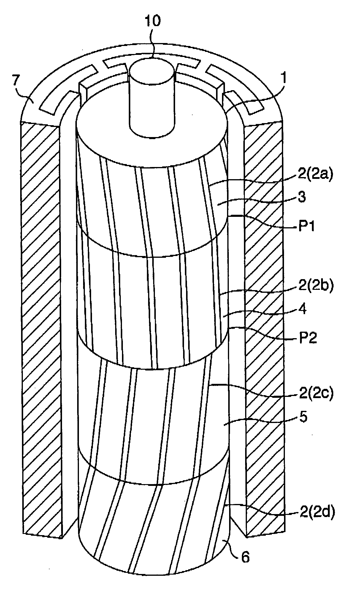
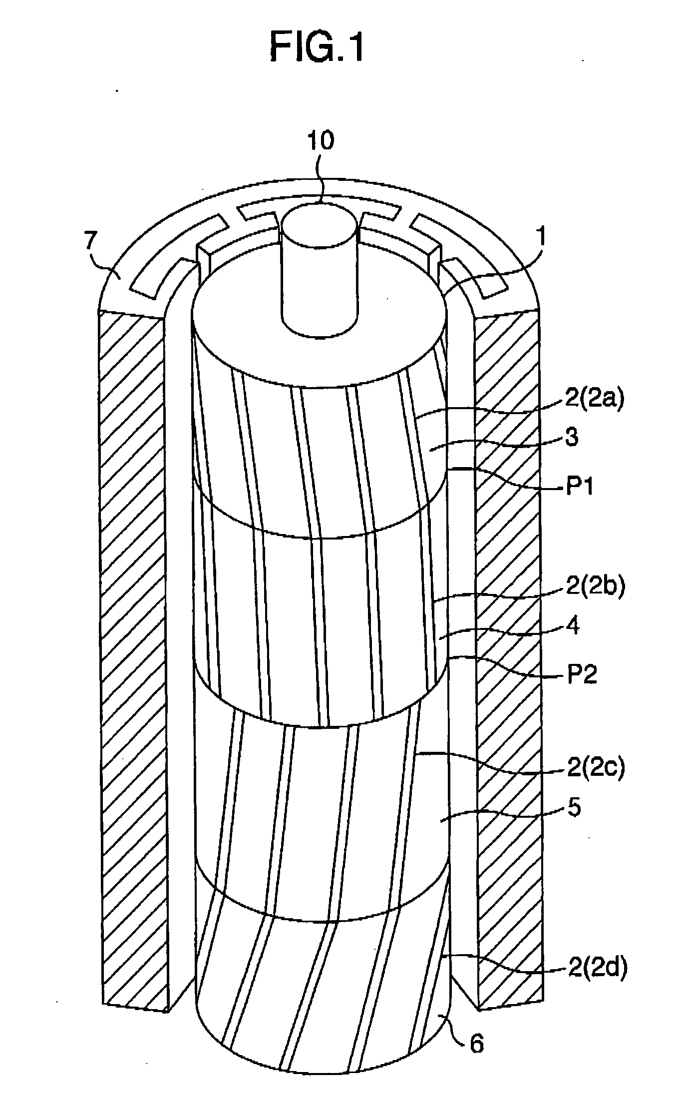
[0069]FIG. 1 is a perspective view illustrating a rotating electric machine incorporating an embodiment of the present invention, and FIG. 2 is a view which shows orthogonal conditions of exciting forces. Table 1 exhibits F, M1 and M2 with respect to orthogonal conditions of the skew patterns.

TABLE 10-Order Mode F1-Order Exciting Force M12-Order Exciting Force M1Exciting force(Moment at x = 0 is set to 0)(Moment at x = ±L / 2 is set to 0)SkewRe{F}Im{F}Re{M1}Im{M1}Re{M1}Im{M2}No Skew2βL00000One Slot Skew002⁢β⁢ ⁢L?x⁢ ⁢?⁢0.64⁢ ⁢β⁢ ⁢L20 (Even Function)0 (Odd Function)4⁢β⁢ ⁢L?x?⁢ ⁢?⁢ ⁢0.41⁢ ⁢β⁢ ⁢L?V-Like Skew000 (Even Function)0 (Even Function)-β⁢ ⁢L?x⁢ ⁢?⁢ -0.32⁢ ⁢β⁢ ⁢L?0λ-Like Skew0002⁢βL?x?⁢ ⁢(2-1)⁢ =0.08⁢ ⁢β⁢ ⁢L?0 (Odd Function)0 (Odd Function)Six-Division Optimum Skew000βL?2⁢x?=0.05⁢ ⁢β⁢ ⁢L?0 (Odd Function)0 (Odd Function)?⁢indicates text missing or illegible when filed

[0070] Referring to FIG. 1, a core of a rotor 1 is composed of a stack of steel plates, which is axially divided in...

embodiment 2

[0098] Referring to FIG. 13 which shows an embodiment of the rotor 1 and the stator 7 of an induction motor as an example of the rotating electric machine 100 according to the present invention, the core of the rotor1 is composed of a stack of the steel plates, which is divided in the direction of the axial length into a plurality of blocks or rotor pieces. The rotor 1 shown in FIG. 13 is composed of rotor pieces 31, 32, 33, 34, 35, 36. A plurality of slots having axial lengths which are equal to those of the rotor pieces 31, 32, 33, 34, 35, 36 which are fitted to a shaft 10 are formed at equal pitches in the circumferential direction so as to obtain oblique skews, and secondary conductors 2a, 2b, 2c, 2d, 2e, 2f defining an effective magnetic opening angles are formed in the slots by aluminum die-casting. There is also shown the stator 7.

[0099] In the embodiment shown in FIG. 13, the secondary conductors 2a, 2b, 2c, 2d, 2e, 2f defining an effective magnetic opening angles are forme...

embodiment 3

[0116] Although explanation has been made of the rotating electric machine itself in the embodiments 1 and 2 as stated above, the configuration incorporated wherein with the rotating electric machine may also exhibit the effect of reduction of vibration and noise.

[0117] A configuration shown in FIG. 21 which is a sectional view, is composed of a rotating electric machine 100 and an inverter 200, and a configuration shown in FIG. 22 which is a sectional view is of a compressor incorporated therein the rotating electric machine 100.

[0118] Further, as to the configuration of the skews, they have not to be straight but they may be curved if the exciting force pattern and the electromagnetic exciting force satisfy the orthogonal condition as shown in FIG. 2.

[0119] The configuration of the W-like skews is shown in FIG. 23 and the configuration of the bolt lightening skews is shown in FIG. 24, as disclosed in the document 5. FIG. 25 shows a list of several skew configurations.


PUM


Abstract

Provided is a rotating electric machine which can restrain vibration and noise induced by a radial electromagnetic force of the rotating electric machine, and in which a rotor is divided into first to fourth four rotating pieces having axial lengths of 0.29 L, 0.71 L, 0.71 L and 0.29 L where 2 L is an axial length of a rotor or stator core, and secondary conductors defining effective magnetic pole opening angles, are arranged being shifted by a value which is equal to a phase difference of electric angle between axial sections of the rotator pieces in order to define skews so that phase differences of electric angles are continuous between axial sections of the first and second rotor pieces, the skews being continuous between the third and fourth rotor pieces but being not continuous between the second and third rotor piece.

Description

BACKGROUND OF THE INVENTION [0001] The present invention relates to a rotating electric machine such as an induction motor or a generator, which can restrains electromagnetic vibration and noise caused by a radial exciting force induced therein. RELATED ART [0002] A large number of rotating electric machines have been used in electric appliances, various OA equipments and the like, and these years, have been becoming more and more installed in electric vehicles. However, rotating electric machines installed in electric vehicles have to have a high output power, and accordingly, cause problems of vibration and nose excited by an electromagnetic exciting force induced by such a high output power. [0003] It has been found that a magnetic path for field magnetic flux induced from magnetic poles of a rotor on moving relative to a stator periodically varies each time when a magnetic pole of the rotor runs across an opening of a slot formed in the stator, and accordingly a magnetic-flux di...

Claims


Application Information

Patent Timeline
IPC IPC(8): H02K16/02H02K17/16
CPCH02K1/22H02K1/27
Inventor NEMOTO, KANAKOTAKANO, YASUSHITAKAHASHI, KAZUHIKOSHIMA, KAZUONISHIHAMA, KAZUO
Owner HITACHI LTD
Why Eureka
Try Eureka