System for remotely monitoring a premise

a technology for remotely monitoring and premise, applied in signaling systems, substation equipment, instruments, etc., can solve the problem of more expensive methods and achieve the effect of more expensive implementation

Inactive Publication Date: 2006-07-27
ACAR MUSTAFA
View PDF2 Cites 15 Cited by
  • Summary
  • Abstract
  • Description
  • Claims
  • Application Information

AI Technical Summary

Benefits of technology

[0008] According to another embodiment of the invention, it is possible to design the BACU and the RACU, so that they can function interchangeably. During the initial setup of the system, a device built as a BACU can automatically or manually reconfigures itself to function as a RACU. Therefore, it is not necessary to manufacture two different types of devices, one functioning as BACU and other functioning as RACU. Even though this method may be more expensive to implement because of the cost of unutilized hardware circuitry in RACU for the CMS communication, however the simplicity of system installation and cost savings involved handling only one type during manufacturing may easily overcome this disadvantage.
[0009] Yet according to another embodiment of the invention, it is possible to design the BACU and RACU, so that they contain a visual display that can be used as a clock to show the real time of the day for that premise. The display will show the real time when there is no other information to display pertinent to BACU or RACU. Also, the user can easily press two buttons simultaneously on the BACU that in turn communicates using with the central monitoring station and receives the updated time information for that location.

Problems solved by technology

Even though this method may be more expensive to implement because of the cost of unutilized hardware circuitry in RACU for the CMS communication, however the simplicity of system installation and cost savings involved handling only one type during manufacturing may easily overcome this disadvantage.

Method used


Image

  • System for remotely monitoring a premise
  • System for remotely monitoring a premise
  • System for remotely monitoring a premise

Examples


Embodiment Construction

[0024] The preferred embodiments of the present invention will hereinafter be described in conjunction with the appended drawings, wherein like designations denote like elements, and further wherein:

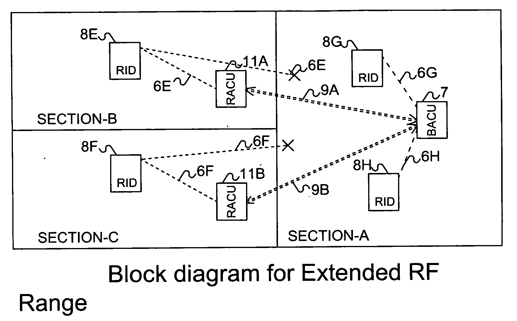
[0025] Emergency systems are often monitored remotely, and information between the monitored premise and the remote monitoring station is transferred back and forth over the existing telephone lines or cellular telephone networks or over long-range wireless communication links or even using the Internet connection.

[0026] It is desirable during an alarm or emergency situation to remotely listen to what is going on in the premise and talk back and forth with the plurality of individuals within the premise.

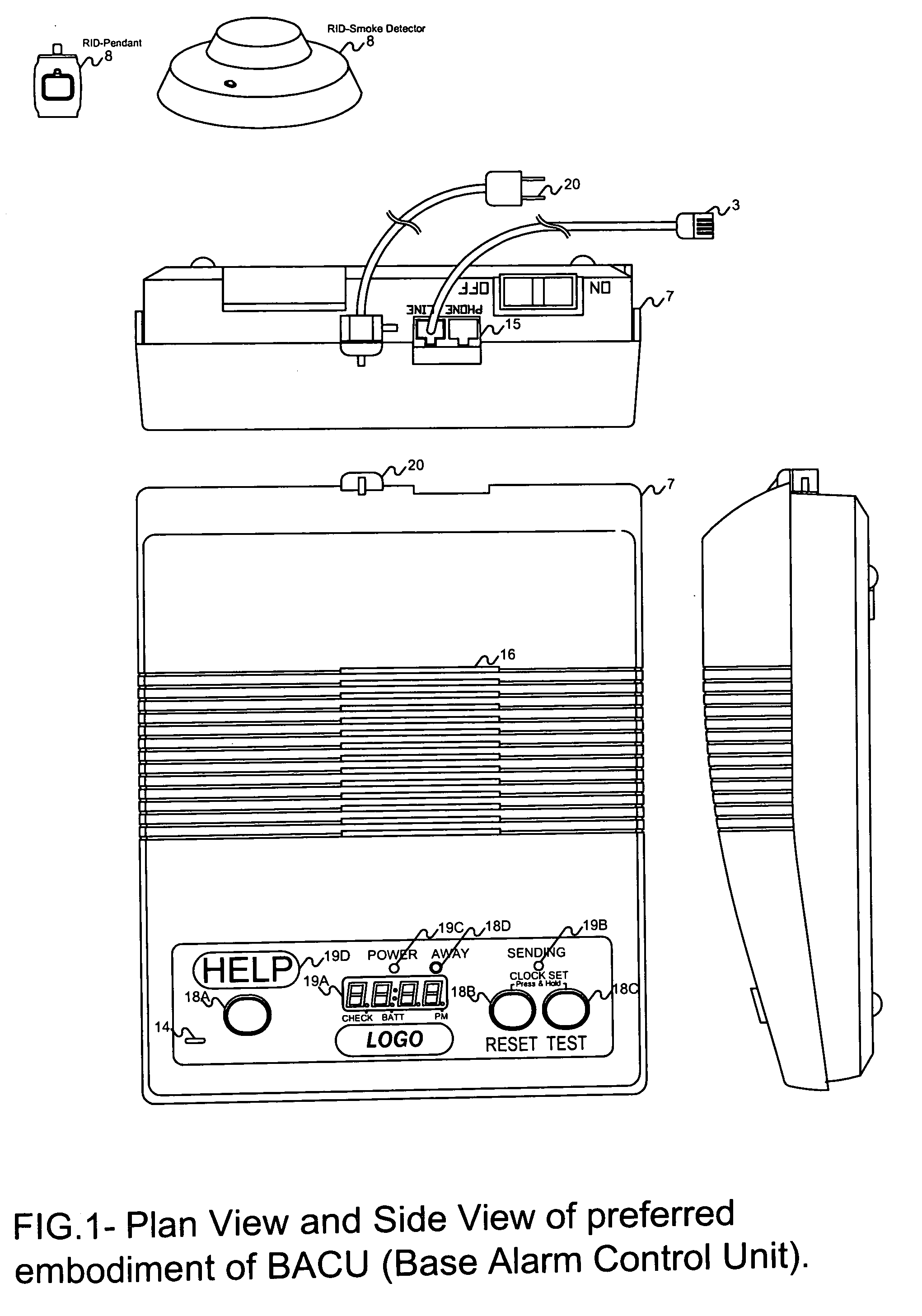
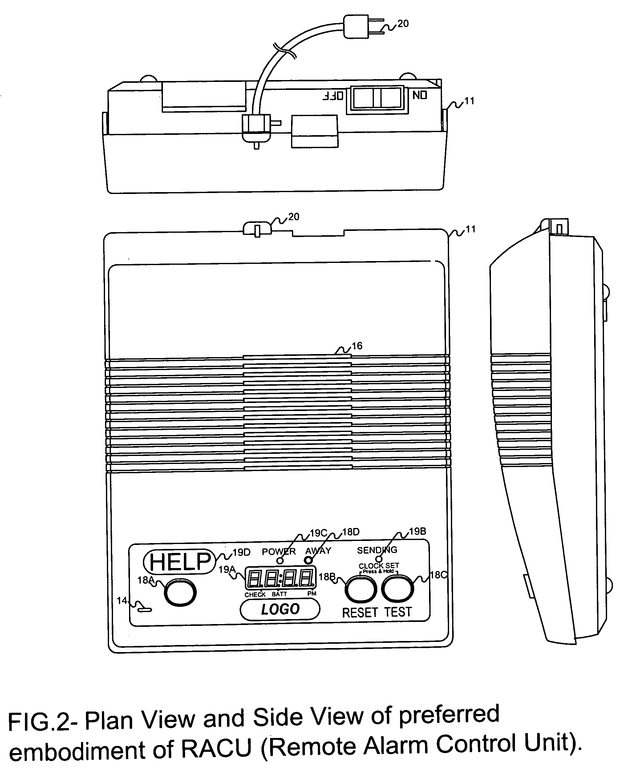
[0027] Referring now to the drawings, the FIG. 1 shows preferred implementation of Base Alarm Control Unit (BACU) (7). The unit has plastic enclosure around the electronic circuitry and system standby battery. User can observe the system visual responses through different display eleme...


PUM


Abstract

A system and method for monitoring a premise in case of an emergency and enabling 2-way voice communications with an individual at every possible location within the monitored premises. The system utilizes a radio frequency 2-way wireless communication link from a centrally located Base Alarm Control Unit on the premise to plurality of Remote Alarm Control Units situated throughout the premise. Remote Alarm Control Units relay the information received from the wireless remote transmitters to the Base Alarm Control Unit thereby increasing the effective useful range of the wireless communication link. The same also establishes a 2-way voice connection between the Central Station operator and the individual who may be located at any possible location within the premise, thereby providing a much more effective handling of the emergency or alarm situation.

Description

[0001] This application claims priority from provisional application entitled, “SYSTEM FOR REMOTELY MONITORING A PREMISE”, Application No. 60 / 641,211, filed Jan. 4, 2005, the entirety of which is incorporated herein by reference.BACKGROUND OF THE INVENTION [0002] Any personal emergency response system or burglary / fire alarm system that exists today consists of a single alarm control unit located at the premise being monitored. This control unit is usually connected to a central monitoring station via one of the possible communication links in order to report a multitude of alarm, emergency or status signals. Multiple emergency or alarm remote initiating devices, whether they are fixed or portable, are used to initiate and convey an emergency or an alarm condition to the alarm control unit. [0003] Some of these alarm control units have 2-way voice capability, containing a microphone and a speaker, capable of transferring the voices and sounds at the premises to the central monitoring...

Claims


Application Information

Patent Timeline
Patent Type & Authority Applications(United States)
IPC IPC(8): G08B1/08H04B1/38G08B29/00
CPCG08B25/003G08B25/009G08B25/016
Inventor ACAR, MUSTAFA
Owner ACAR MUSTAFA
Why Eureka
Try Eureka