
Highly sensitive inertial mouse

a mouse and inertial technology, applied in the field of high-sensitivity inertial mouse, can solve the problems of displacement not being detected on a transparent and smooth surface, requiring large power consumption for optical image processing skill, and no other technically made mouse has been used on the mark

Inactive Publication Date: 2006-07-27
CHIC TECH CORP +1
View PDF7 Cites 32 Cited by
  • Summary
  • Abstract
  • Description
  • Claims
  • Application Information

AI Technical Summary

Benefits of technology

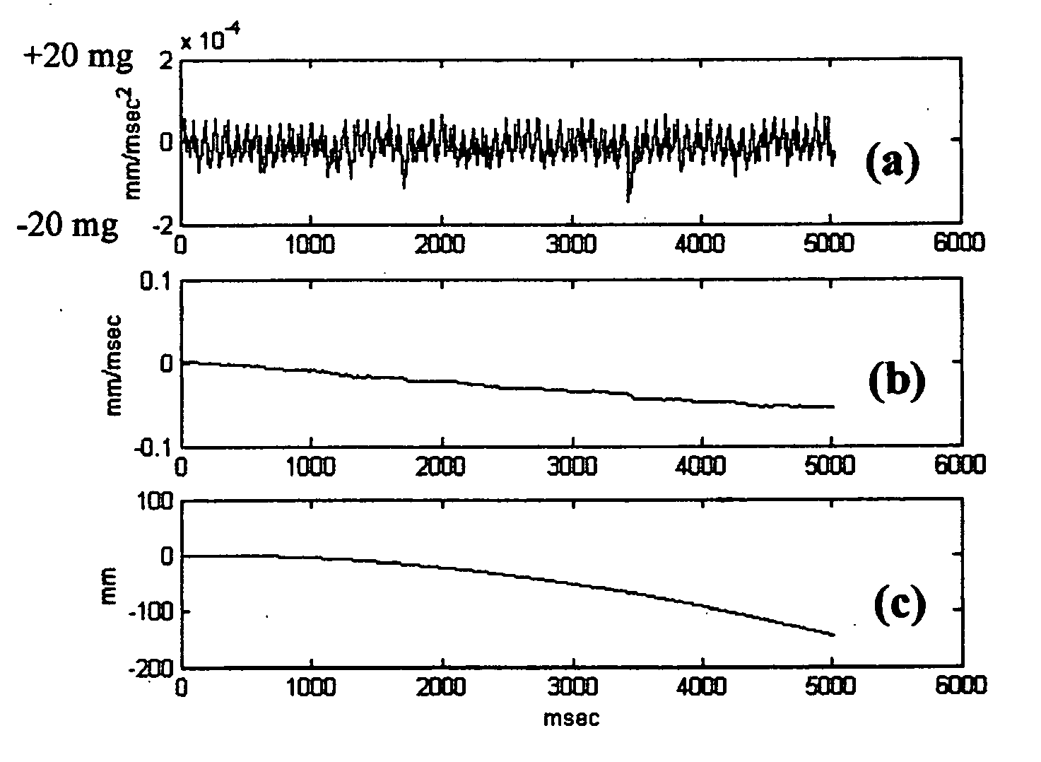
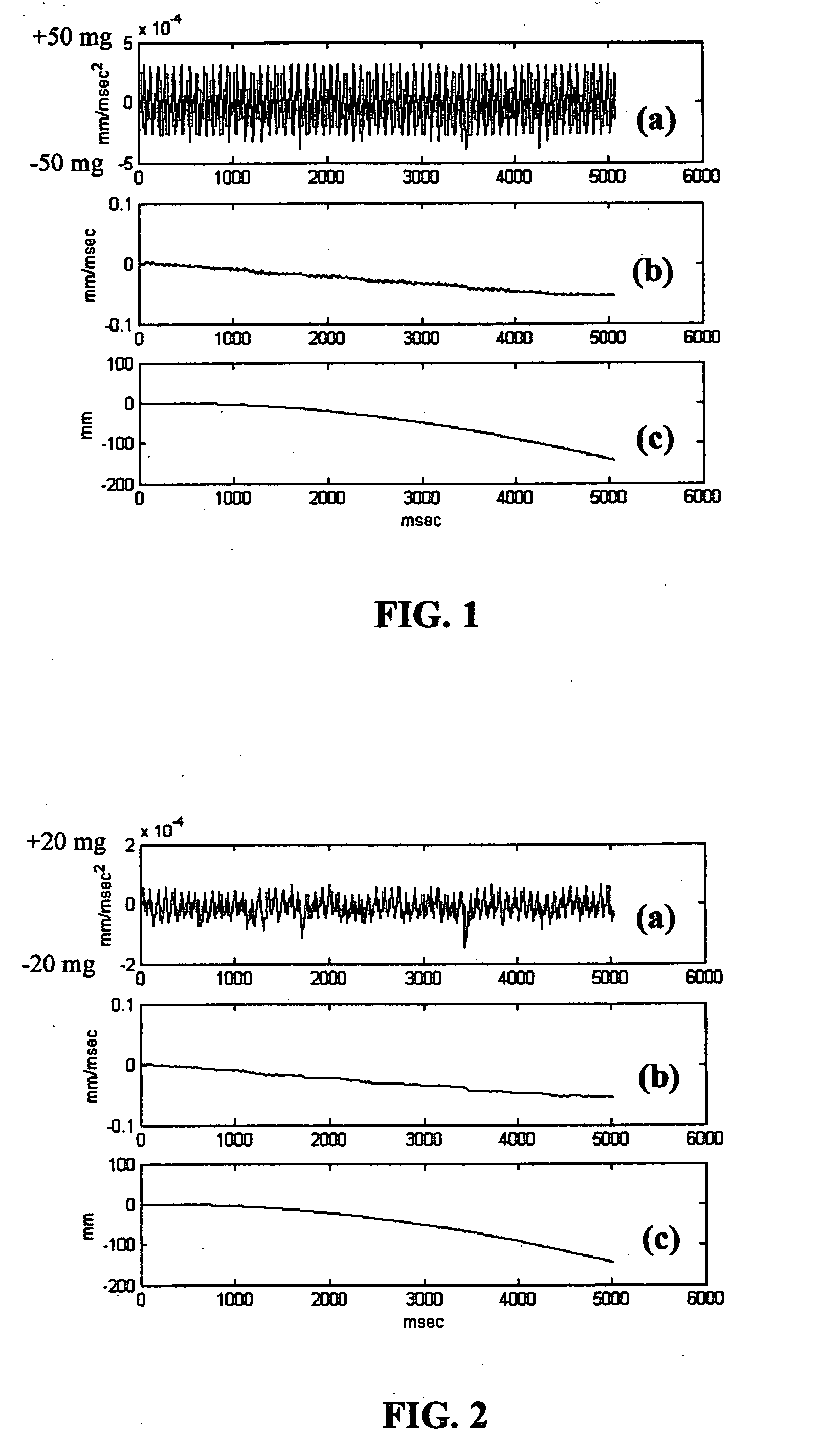
[0009] The present invention relates to a highly sensitive inertial mouse mainly including collecting of data, noise cancellation, setting of threshold of dead zone, tracking of baseline, calculation of displacement and adjustment of sensitivity being the six basic signal processing principles wherein: the noise cancellation uses all kinds of noise canceling techniques in order to decrease internal and external noise thus increasing sensitivity.
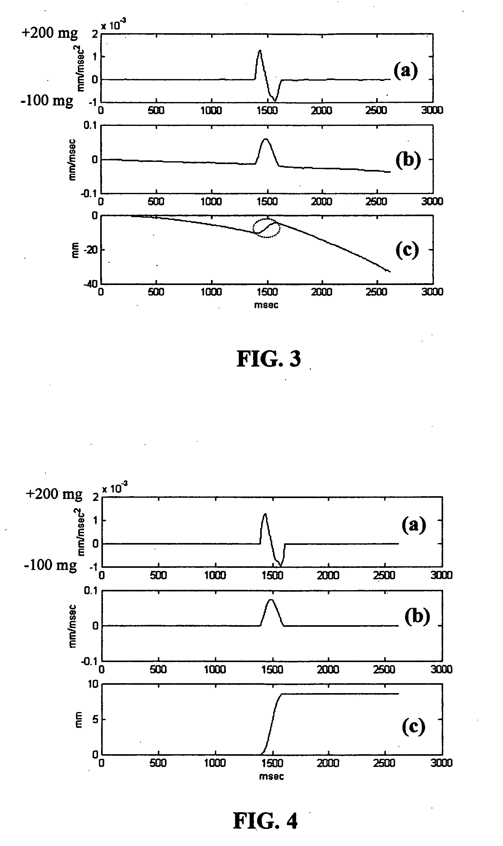
[0011] The present invention relates to a highly sensitive inertial mouse mainly including collection of data, noise cancellation, setting of threshold of dead zone, tracking of baseline, calculation of displacement and adjustment of sensitivity consisting the six basic signal processing principles wherein: the tracing of baseline uses all kinds of techniques for dynamic tracing of the baseline of the inertial sensor at zero acceleration, eliminates any baseline movement caused by a drift in the sensor of the baseline itself or rough operating table surface in order to avoid miscalculations and unexpected displacements.

Problems solved by technology

The roller method is detected by a turning optical encoder disk whereas the optics mouse uses an optical image processing skill requiring large power consumption and displacement cannot be detected on a transparent and smooth surface.
Laser optics mice have been introduced on the market nowadays to solve the problem of transparent and smooth surface but apart from using optics technique in the manufacturing of computer mice, no other technically made mouse has been used on the market.
Hence, it cannot be released on the market.

Method used


Image

  • Highly sensitive inertial mouse
  • Highly sensitive inertial mouse
  • Highly sensitive inertial mouse

Examples


Embodiment Construction

[0042] The manufacturing method of the present mouse should all have the following data processing methods:

(1) Collecting of Data

[0043] Due to A / D converter converting analog signal of inertial sensor to different forms of digital signal, some are indicated by the frequency like FORD company; some are indicated by pulse width like Analog Device company (known as AD company), some are output by serial signals and some by parallel signals. To sum up, the different forms of signals have to be converted to a practical data representing inertial acceleration before any further signal processing. For example, for frequency signals, just connect the signals to the counter to count the number of passing pulses in every 10 msec and the magnitude of inertial acceleration will be known. This also applies to AD inertial sensor using an internal oscillator and counter to calculate the duration of pulse width and further use the formula provided by AD companies to convert pulse width to practi...


PUM


Abstract

A highly sensitive inertial mouse is in particular to one using an MEMS(Micro-Electrical-Mechanical System)inertial sensitive principle; the mouse uses MEMS inertial sensitive principle including a two-dimensional or three-dimensional inertial sensors or accelerometers and with the use of signal processing methods such as collecting of data, noise cancellation, setting of threshold of dead zone, tracking of baseline, calculation of displacement and adjustment of sensitivity and so on, enable the MEMS sensor acting as the manufacturing component of a computer mouse; furthermore, the present invention is not only light and energy saving, but also obviates the drawbacks of high power consumption of optics mice or easy-dirt collection of roller mice. Moreover, with the increase in sensitivity, the bottleneck in the manufacturing of inertial mouse is overcome such that the functions of MEMS inertial mouse is very stable and reliable and can be easily used.

Description

BACKGROUND OF THE INVENTION [0001] 1. Field of the Invention [0002] The present invention relates to a highly sensitive inertial mouse and in particular to one using MEMS inertial sensitive principle to produce a highly sensitive computer mouse. [0003] 2. Description of the Related Art [0004] Reference: U.S. Pat. No. 4,787,051 “Inertial mouse system” as described in the copies of documents attached. Recently, the manufacturing of computer mice is mainly either roller or optics mice and both apply optics principle to detect the mouse displacement. The roller method is detected by a turning optical encoder disk whereas the optics mouse uses an optical image processing skill requiring large power consumption and displacement cannot be detected on a transparent and smooth surface. Laser optics mice have been introduced on the market nowadays to solve the problem of transparent and smooth surface but apart from using optics technique in the manufacturing of computer mice, no other techni...

Claims


Application Information

Patent Timeline
IPC IPC(8): G09G5/08
CPCG06F3/0346G06F3/03543G06F3/0383
Inventor WU, CHUNG-MINLUO, CHING-HSING
Owner CHIC TECH CORP
Learn More