
Mounted structure, liquid droplet ejection head, liquid droplet ejection apparatus and manufacturing method

Inactive Publication Date: 2006-07-27
SEIKO EPSON CORP
View PDF3 Cites 22 Cited by
  • Summary
  • Abstract
  • Description
  • Claims
  • Application Information

AI Technical Summary

Benefits of technology

[0008] An advantage of some aspects of the invention is to provide a structure capable of mounting, even if the wiring has a narrow pitch semiconductor element, a method of manufacture of a device, a liquid droplet ejection head and its method of manufacture.

Problems solved by technology

If the distance between the piezoelectric elements is small, connection between the multiple piezoelectric elements, and between the respective wiring and the driver IC, by the wire bonding method is difficult.

Method used


Image

  • Mounted structure, liquid droplet ejection head, liquid droplet ejection apparatus and manufacturing method
  • Mounted structure, liquid droplet ejection head, liquid droplet ejection apparatus and manufacturing method
  • Mounted structure, liquid droplet ejection head, liquid droplet ejection apparatus and manufacturing method

Examples


first embodiment

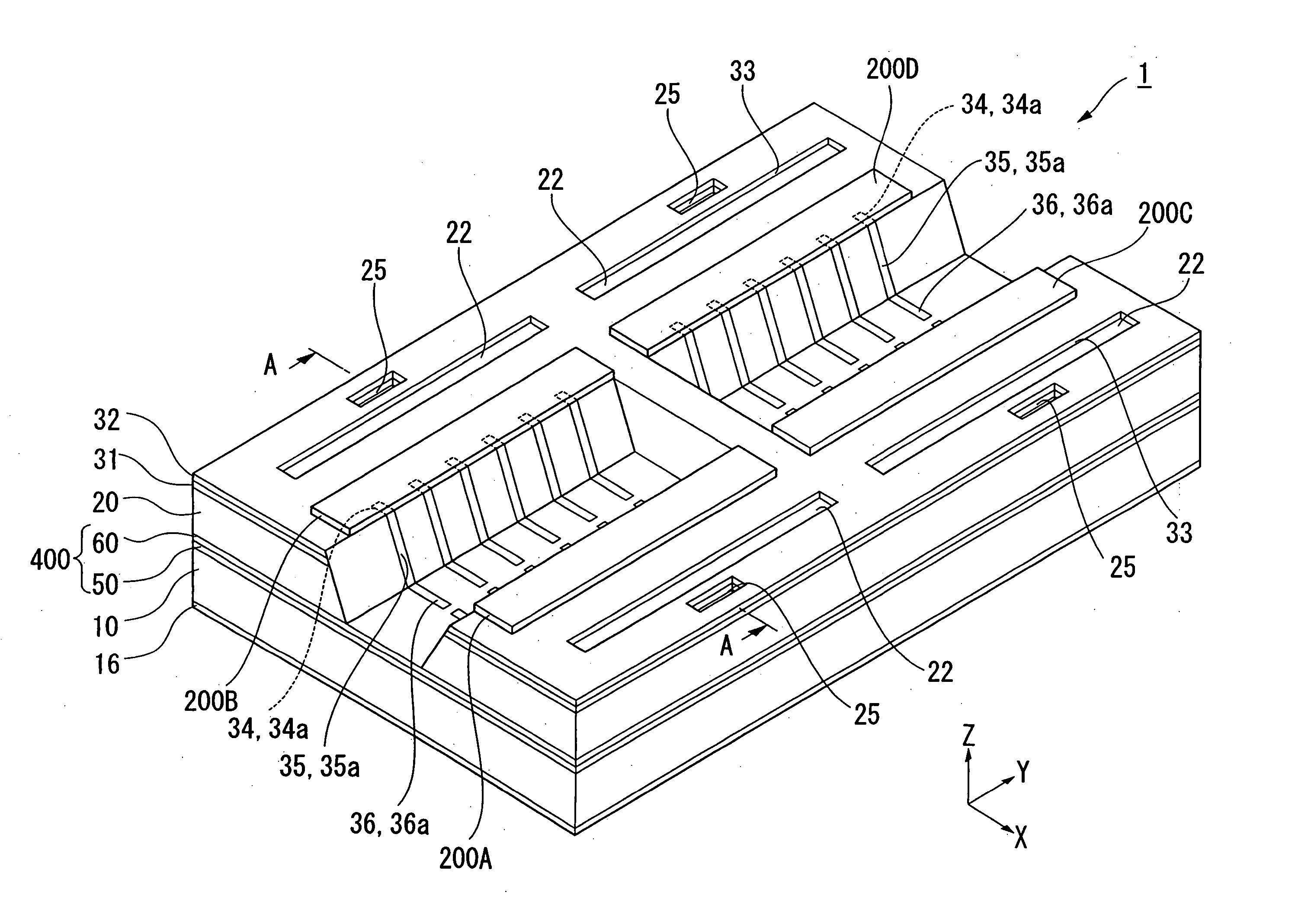
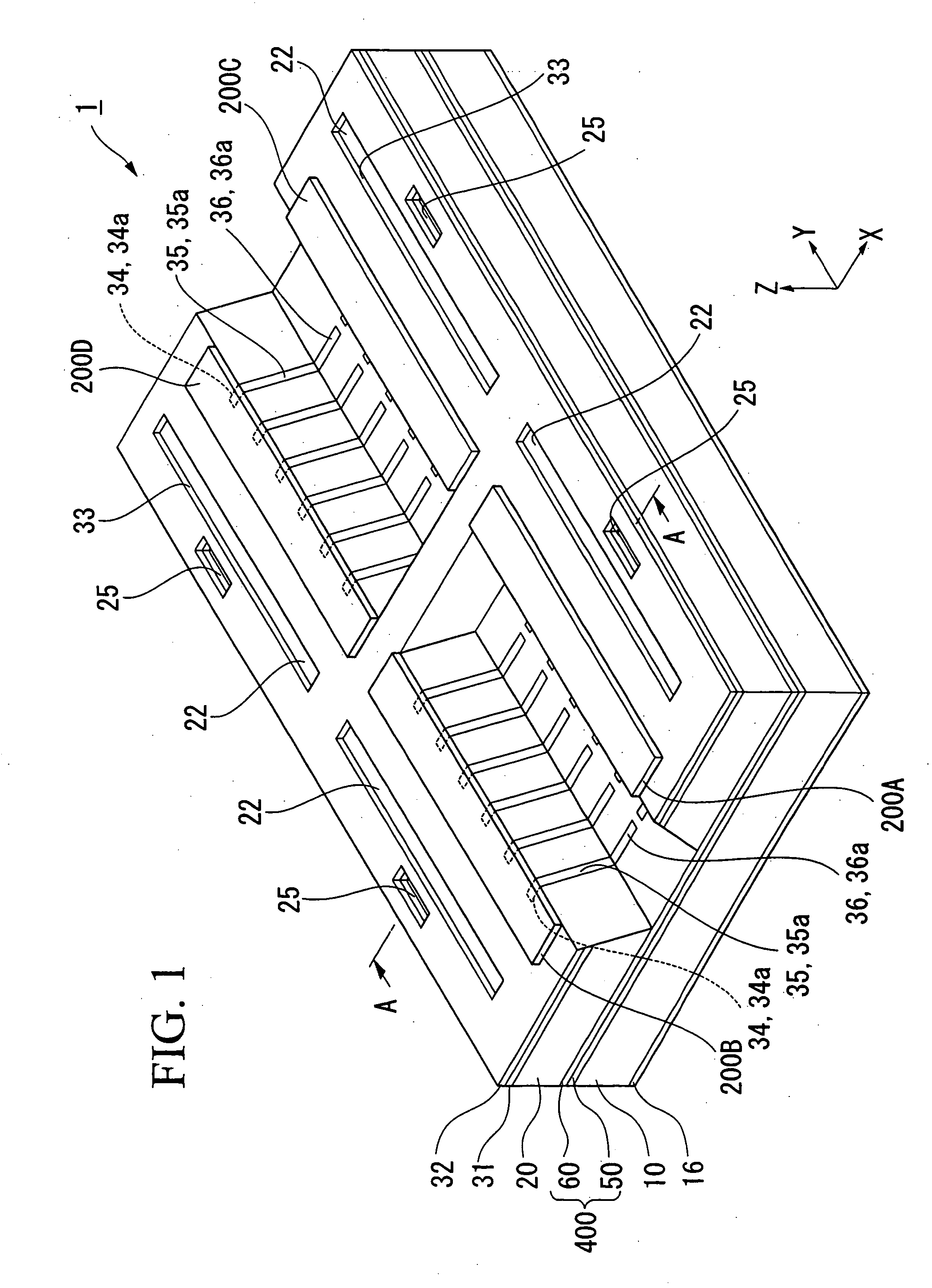
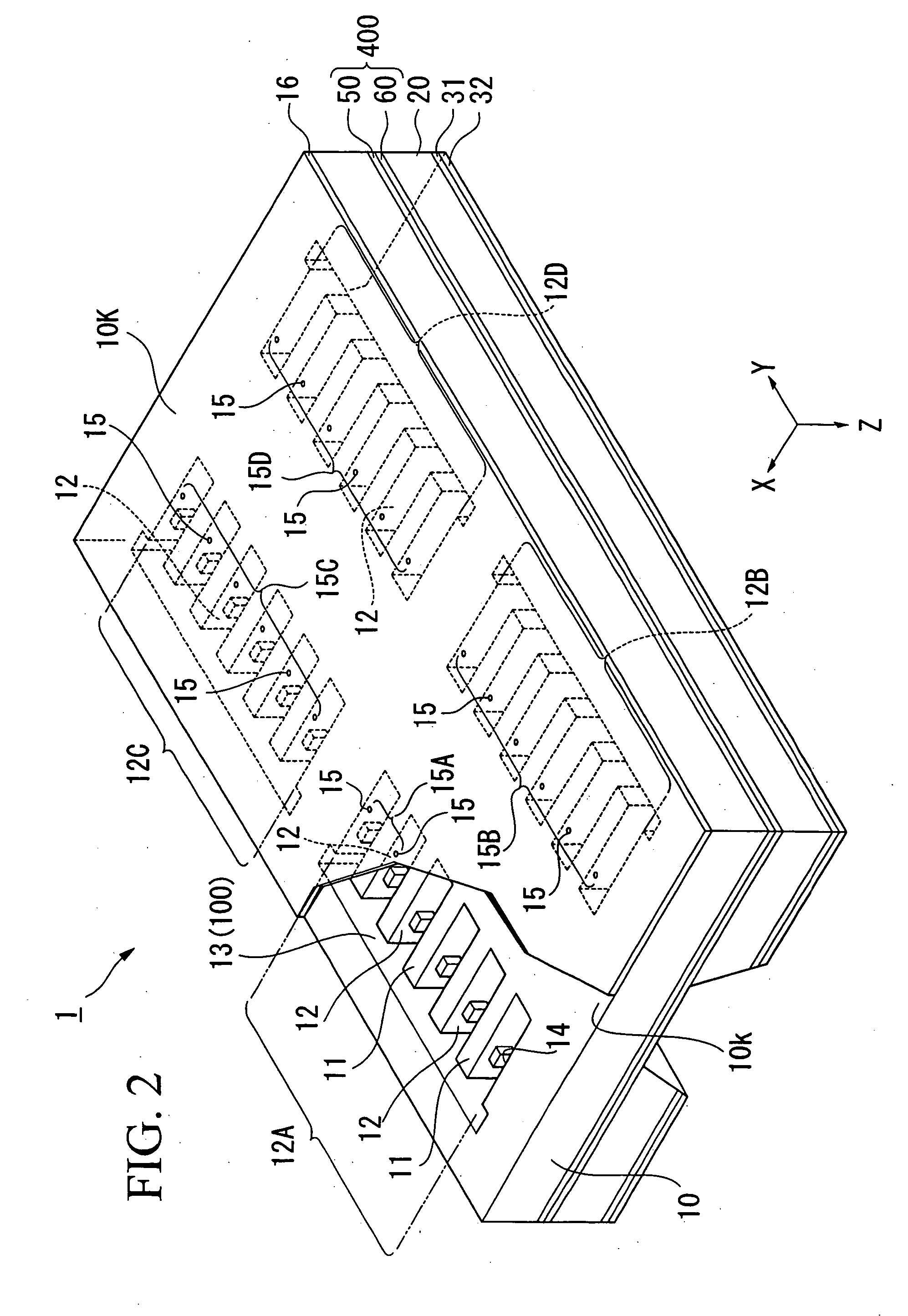
[0100] An explanation of a first Embodiment of a liquid droplet ejection head according to the present invention is described hereafter with reference FIGS. 1 to 3. FIG. 1 is a perspective view of an embodiment of the liquid droplet ejection head, FIG. 2 is a partially fragmented diagram of a perspective view in which the liquid droplet ejection head is viewed from below, and FIG. 3 is a cross-sectional diagram of line A-A, in FIG. 1.

[0101] As shown in FIG. 3, a liquid droplet ejection head 1 of the present Embodiment turns functional fluid into droplets, and ejects them from a nozzle. The liquid droplet ejection head 1 is provided with a flow path forming substrate (first member, first substrate) 10, a pressurizing chamber 12 which communicates with a nozzle aperture 15 from which the liquid droplets are ejected, and a piezoelectric element (driven element) 300 which produces a pressure change in the pressurizing chamber 12 arranged on the upper surface of the pressurizing chamber...

second embodiment

[0159] An explanation of the second embodiment of the liquid droplet ejection head is provided hereafter, with reference to FIG. 7.

[0160]FIG. 7 is an explanatory diagram of the mounting structure according to the second embodiment, and is an enlarged view of part C of FIG. 8B. As shown in FIG. 7, in the liquid droplet ejection head according to the second embodiment, in addition to the fact that the second wiring 34 extends to a position facing the connection terminal 44 of the semiconductor element 200, there is the point that an electrically conductive protrusion 45 is protrudingly formed facing the second wiring 34, in which regard it differs from the first embodiment. A detailed explanation concerning construction parts which are the same as in the first embodiment is omitted.

[0161] In the second embodiment, the second wiring 34 formed on the upper surface of the reservoir forming substrate 20 extends to a position facing the connection terminal 44 of the semiconductor element...

third embodiment

[0169] An explanation is provided concerning the third embodiment of the liquid droplet ejection head of the present invention, with reference to FIGS. 9 to 11. FIG. 9 is a perspective view showing the third Embodiment of the liquid droplet ejection head, and FIG. 10 is a partially broken diagram of the oblique construction diagram in which the liquid droplet ejection head is viewed from below, and FIG. 11 is a cross-sectional diagram along the line A-A of FIG. 9.

[0170] As shown in FIG. 11, the liquid droplet ejection head 1 of the present embodiment emits functional liquid in liquid droplet form from the nozzle. The liquid droplet ejection head 1 is provided with a pressurizing chamber 12 which is coupled to the nozzle aperture 15 from which the liquid droplets are ejected, and the piezoelectric element (driven element) 300 which produces pressure changes in the pressurizing chamber 12 arranged on the upper surface of the pressurizing chamber 12, and the reservoir forming substrat...


PUM

PropertyMeasurementUnit
Angleaaaaaaaaaa
Electrical conductoraaaaaaaaaa
Photosensitivityaaaaaaaaaa

Abstract

A liquid droplet ejection head that ejects liquid droplets through deformation of a driven element, includes: a first substrate having a pressurizing chamber with a nozzle aperture that ejects liquid droplets, and a first surface on which is formed a first wiring electrically connected to the drive element; a second substrate disposed on the first surface of the first substrate and covering the driven element, the second substrate having a second surface and a side surface, the second surface facing in a same direction as the first surface of the first substrate and on which is formed a second wiring, the side surface on which is formed a third wiring that combines the first wiring and the second wiring; a semiconductor element disposed on the second surface of the second substrate, and which drives the driven element; and plating that electrically connects the first wiring, the second wiring, the third wiring, and a connection terminal of the semiconductor element.

Description

CROSS-REFERENCE TO RELATED APPLICATION [0001] This application claims priority to Japanese Patent Application No. 2005-17951, filed Jan. 26, 2005, Japanese Patent Application No. 2005-17952, filed Jan. 26, 2005, Japanese Patent Application No. 2005-78974, filed Mar. 18, 2005, Japanese Patent Application No. 2005-309522, filed Oct. 25, 2005, the contents of which are incorporated herein by reference. BACKGROUND [0002] 1. Technical Field [0003] The present invention relates to mounted structure, liquid droplet ejection head, liquid droplet ejection apparatus, and manufacturing method thereof. [0004] 2. Related Art [0005] A liquid droplet ejection method (ink jet method) is proposed for use when manufacturing an image forming device or micro device. The liquid droplet ejection method is a method for forming a desired pattern ejected onto a substrate, in which a functional liquid which includes a material for forming the device or for forming the image is made into liquid droplets and i...

Claims


Application Information

Patent Timeline
IPC IPC(8): B41J2/045
CPCB41J2/14233B41J2002/14419B41J2002/14491H05K1/0306Y10T29/49126H05K3/32H05K3/403H01L2224/16Y10T29/49401H05K3/185H01L2224/0554H01L2224/0557H01L2224/05571H01L2224/05573H01L2224/05624H01L2224/05639H01L2224/05644H01L2224/05647H01L2224/05655H01L2224/05671H01L2924/00014H01L2224/05599H01L2224/0555H01L2224/0556A01B49/06A01C3/06A01C5/064A01C5/066
Inventor YODA, TSUYOSHI
Owner SEIKO EPSON CORP
Learn More