Method and measuring device for contactless measurement of angles or angle changes on objects

a technology of angle change and measurement method, which is applied in the direction of optical properties testing, instruments, surveying and navigation, etc., can solve the problems of manual reading and may not be easily automated, requires fixed reference distance, and expensive receivers with optoelectronic converters and special analysis electronics

Active Publication Date: 2006-07-27
HOFBAUER ENGELBERT
View PDF6 Cites 17 Cited by
  • Summary
  • Abstract
  • Description
  • Claims
  • Application Information

AI Technical Summary

Benefits of technology

[0024] The screen may be designed in such a way that it has two or more openings positioned in a suitable way, whose geometries are known and which allow exact determination of the screen image size on the detector. The imaging scale may be ascertained via the determination of the screen image size and wherein the focal intercept and the measurement distance respectively may be determined via the known focal width of the optical system.

Problems solved by technology

The disadvantage in this method is the required fixed reference distance between measuring device and mirror in order to obtain a sharp image on the matte disk, which must be read manually and may not be automated easily.
In addition, a special, complex, and costly receiver having the optoelectronic converters and special analysis electronics is necessary for automatic ascertainment of the measured values due to the relatively great enlargement of the image.
Furthermore, the number and size (packing density) of the optoelectronic converters are limited, so that the resolution and measuring range are too low for most applications.
A disadvantage in these arrangements is that with increasing measurement distance, i.e., as the distance becomes greater between mirror and autocollimator, the angle measurement range is reduced because of shadowing through screen effects.
The problem in this case is that continuous measurement within a large measuring range is not possible.
However, this system also functions for large angles up to 30° only at very small distances between test object and receiver system, since the lens opening of the receiver collimator also vignettes and also does not solve the problems described above.

Method used


Image

  • Method and measuring device for contactless measurement of angles or angle changes on objects
  • Method and measuring device for contactless measurement of angles or angle changes on objects
  • Method and measuring device for contactless measurement of angles or angle changes on objects

Examples


Embodiment Construction

[0035] In the method according to the present invention, a beam bundle is used which originates from a homogeneously illuminated planar radiation field and transilluminates the screen uniformly. Optical, incoherent radiation may be used as the radiation, visible, monochromatic light between 400 and 780 nm in the exemplary embodiment, IR, UV, and the entire further range of the electromagnetic spectrum from gamma radiation via x-ray radiation up to microwave radiation also being conceivable. Furthermore, monochromatic and / or coherent or partially coherent radiation sources are also conceivable.

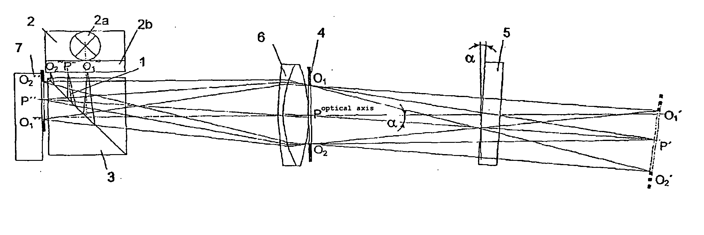
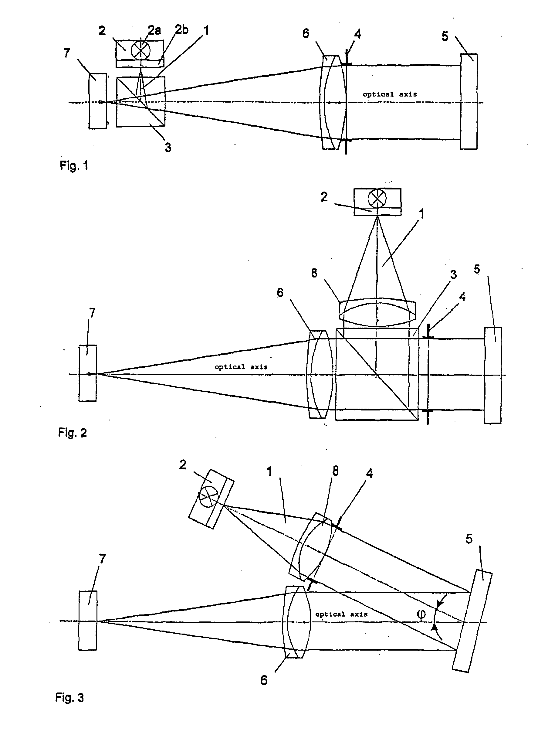
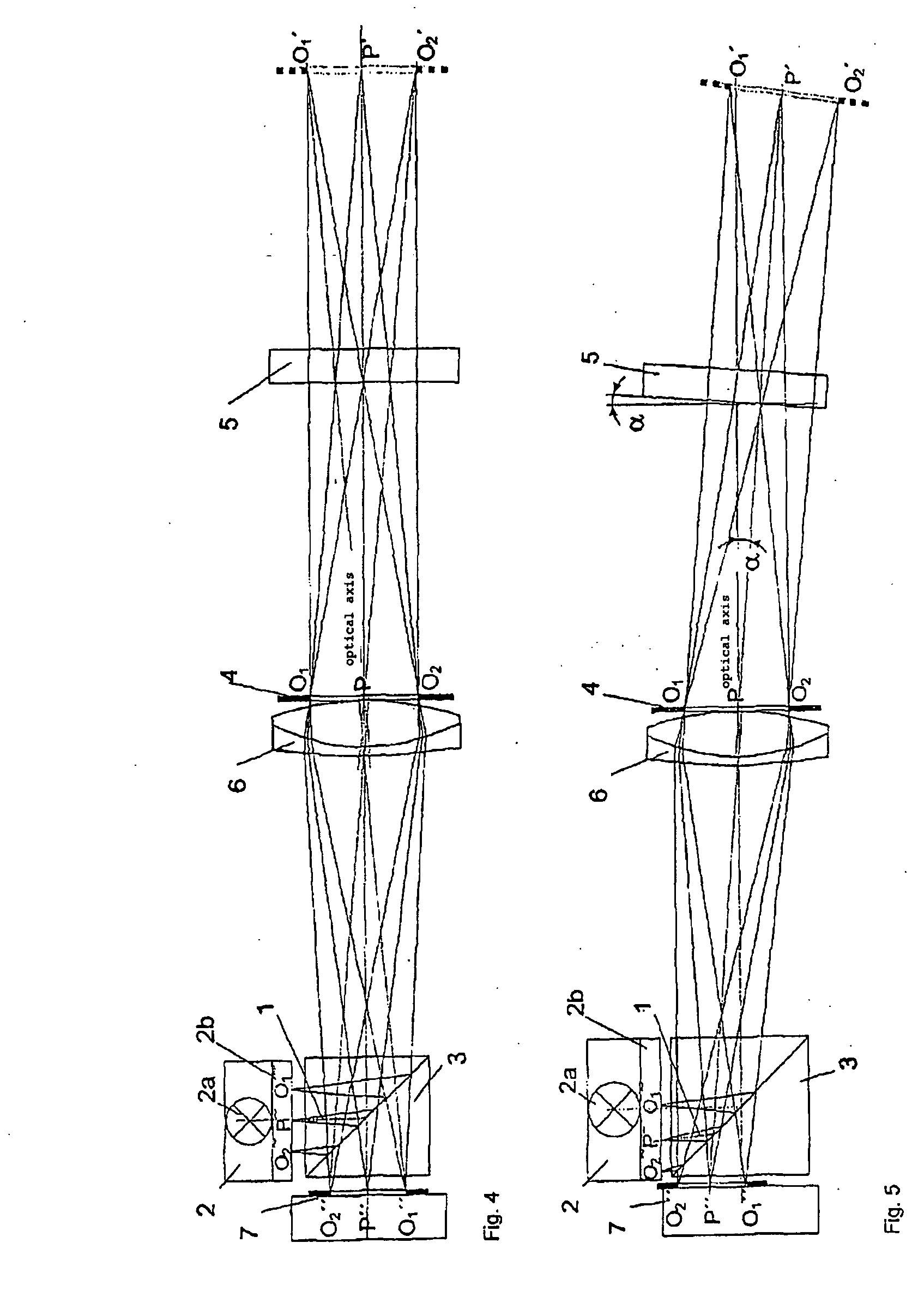
[0036] The screen is subsequently first imaged on a reflecting surface subjected to the angle change at the imaging scale 1 and subsequently the virtual image of the screen arising at double the distance from screen to reflecting surface is imaged via the optical system on a detector surface.

[0037] The present invention is based on the idea of analyzing a lateral screen image displacement on ...


PUM


Abstract

The invention relates to a method for the contactless measurement of angles or angle modifications, distances or lateral displacements in objects. According to said method, an aperture is transilluminated by means of a ray bundle and after being reflected by a distant reflective element, which generates or is subjected to the angles, angle modifications or lateral displacements that are to be measured, is projected onto a detector surface by an optical system. The image of the aperture on the detector surface is captured, the position of the aperture image is determined in relation to a reference point on the detector surface and the measured value of the angle modification or lateral displacement is calculated using the distance of the centre of the image from the reference point. The invention also relates to an angle or height measuring device.

Description

CROSS-REFERENCE TO RELATED APPLICATIONS [0001] This application is a continuation application of the international patent application Serial No. PCT / DE2004 / 001293 filed Jun. 21, 2004, the disclosure of which is hereby incorporated herein by reference.BACKGROUND OF THE INVENTION [0002] The present invention relates to a method and a device for measuring angles or angle changes on objects. [0003] Measuring systems according to the reflection method, which are used for measuring camber and toe of motor vehicles, are known from Patent Specifications CH 454 477, CH 451 532, and DE 2759 556 C2. In this case, a measuring scale is imaged using a projector over the reflecting surface, which is subjected to the angle change, on a matte disk and / or on a matte disk having optoelectronic converters. The disadvantage in this method is the required fixed reference distance between measuring device and mirror in order to obtain a sharp image on the matte disk, which must be read manually and may no...

Claims


Application Information

Patent Timeline
Patent Type & Authority Applications(United States)
IPC IPC(8): G01B11/26G01B11/14G01C3/20
CPCG01B11/26G01M11/0221
Inventor HOFBAUER, ENGELBERT
Owner HOFBAUER ENGELBERT
Why Eureka
Try Eureka