Nano-enhanced Raman spectroscopy-active nanostructures including elongated components and methods of making the same

Active Publication Date: 2006-07-27
HEWLETT PACKARD DEV CO LP
View PDF25 Cites 32 Cited by
  • Summary
  • Abstract
  • Description
  • Claims
  • Application Information

AI Technical Summary

Benefits of technology

[0017] While the specification concludes with claims particularly pointing out and distinctly claiming that which is regarded as the present invention, the advantage

Problems solved by technology

As a result, powerful, costly laser sources typically are used to generate high intensity excitation radiation to increase the weak Raman signal for detection.
Also, the inability to produce such NERS-active structures is impe

Method used


Image

  • Nano-enhanced Raman spectroscopy-active nanostructures including elongated components and methods of making the same
  • Nano-enhanced Raman spectroscopy-active nanostructures including elongated components and methods of making the same
  • Nano-enhanced Raman spectroscopy-active nanostructures including elongated components and methods of making the same

Examples


Embodiment Construction

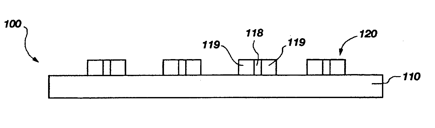
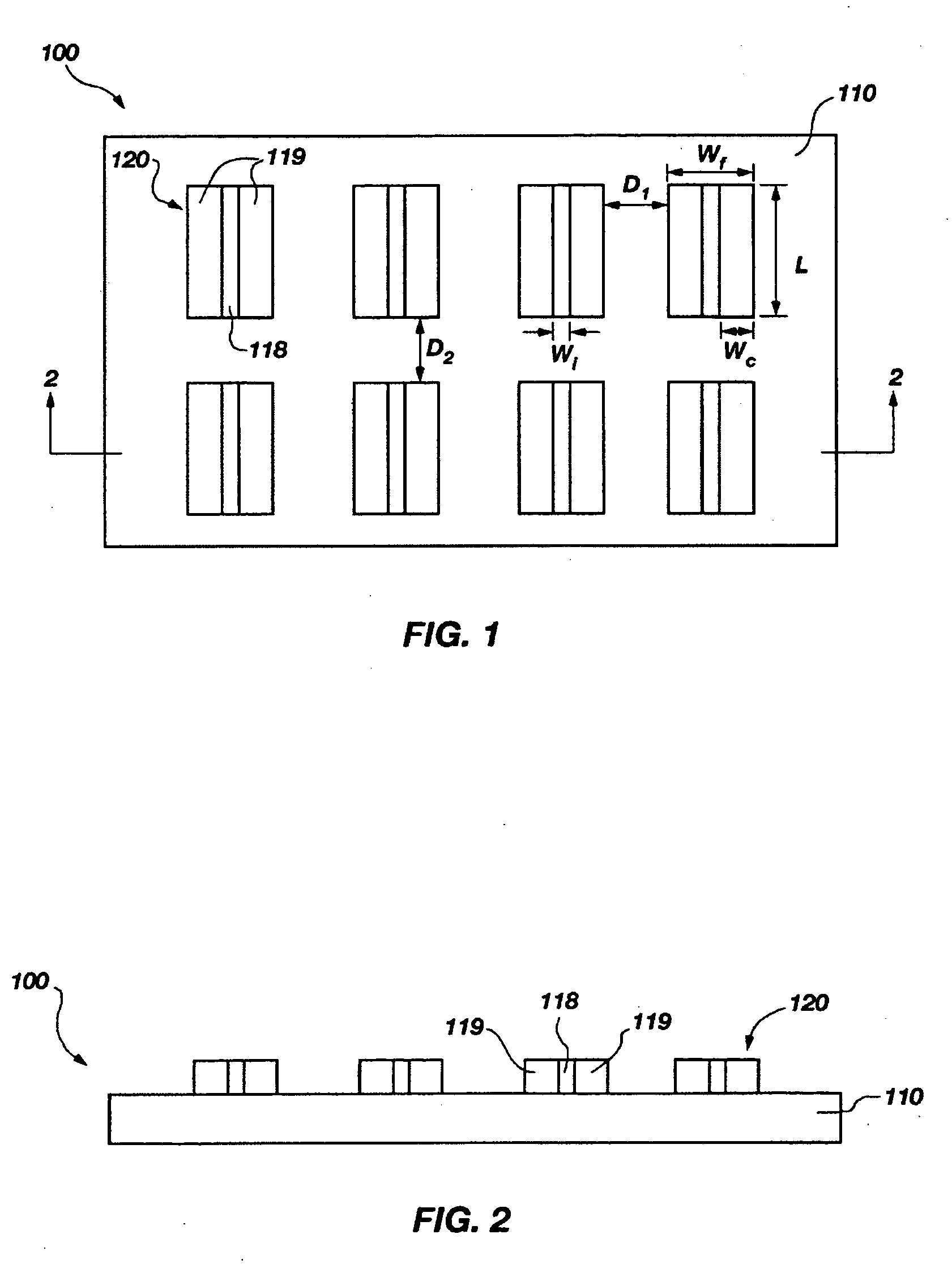
[0025] The present invention, in a number of embodiments, includes NERS-active structures including elongated features having nanoscale dimensions, methods for forming NERS-active structures, NERS systems including NERS-active structures, and methods for performing NERS using such systems.

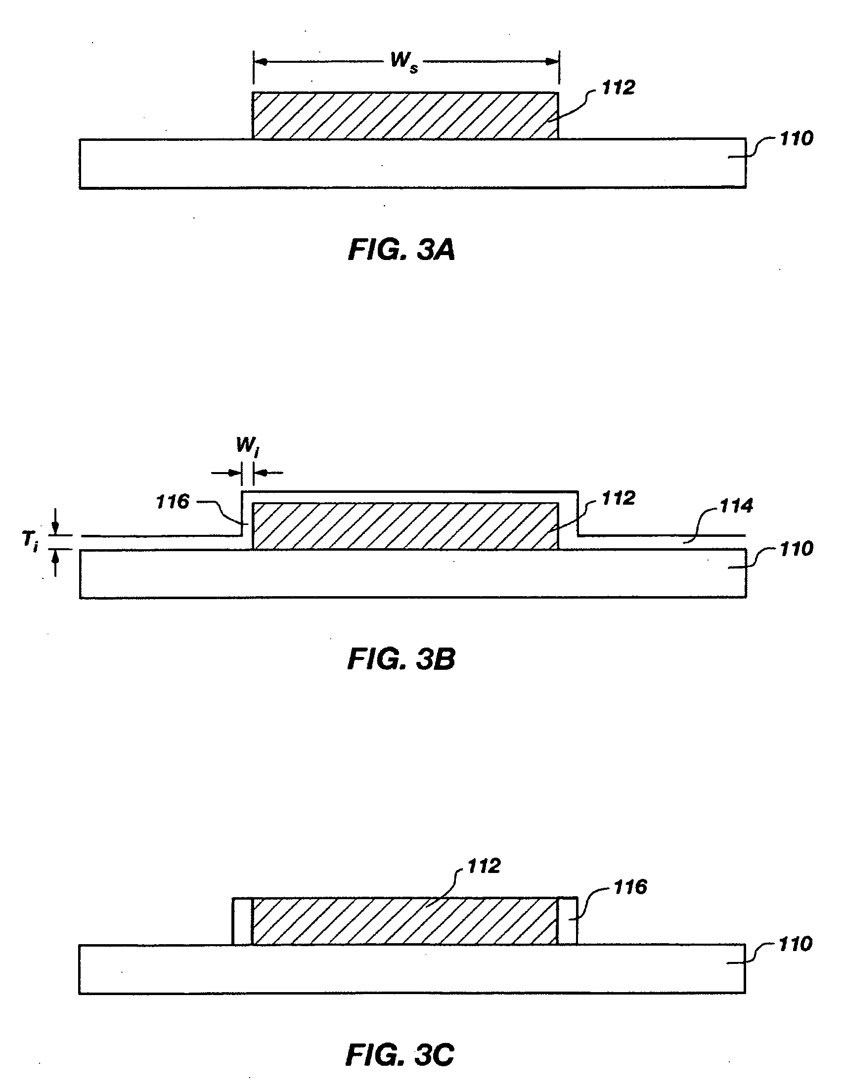
[0026] The methods disclosed herein are drawn to the fabrication of NERS-active structures, including nanoscale features having well controlled size, shape, and spacing, which allows for improved enhancement of the Raman scattered signal intensity relative to previous NERS-active structures.

[0027] It should be understood that the illustrations presented herein are not meant to be actual views of any particular NERS-active structure, but are merely idealized representations which are employed to describe the present invention. Additionally, for ease of discussion, elements common to FIGS. 1 through 7 retain the same numerical designation.

[0028] An exemplary embodiment of an NERS-active structure ...


PUM


Abstract

An NERS-active structure is disclosed that includes a substrate and at least one elongated component disposed on the substrate. The at least one elongated component may include two conducting strips including an NERS-active material and an insulating strip positioned between the two conducting strips. Alternatively, the at least one elongated component may include a homogeneous component. An NERS system is also disclosed that includes an NERS-active structure. Also disclosed are methods for forming an NERS-active structure and methods for performing NERS with NERS-active structures.

Description

FIELD OF THE INVENTION [0001] The invention relates to nano-enhanced Raman spectroscopy (NERS). More particularly, the invention relates to NERS-active structures including features having nanoscale dimensions, methods for forming NERS-active structures, and methods for performing NERS using NERS-active structures. BACKGROUND OF THE INVENTION [0002] Raman spectroscopy is a well-known technique for performing chemical analysis. In conventional Raman spectroscopy, high intensity monochromatic light provided by a light source, such as a laser, is directed onto an analyte (or sample) that is to be chemically analyzed. A majority of the incident photons are elastically scattered by the analyte molecule. In other words, the scattered photons have the same energy, and thus the same frequency, as the photons that were incident on the analyte. However, a small fraction of the photons (i.e., about 1 in 107 photons) are inelastically scattered by the analyte molecules. These inelastically scat...

Claims


Application Information

Patent Timeline
IPC IPC(8): G01J3/44G01N21/65
CPCG01N21/658
Inventor KAMINS, THEODORE I.WILLIAMS, R. STANLEY
Owner HEWLETT PACKARD DEV CO LP
Why Eureka
Try Eureka