
Cylindrical irradiance-mapping lens and its applications to LED shelf-lighting

a technology of irradiance mapping and lens, applied in the direction of lighting support devices, instruments, condensers, etc., can solve the problems of linear lenses, inherently difficult to tailor linear lenses, and complicating the lateral flux control necessary for uniform illumination, etc., to achieve uniform output illumination

Active Publication Date: 2006-07-27
SEOUL SEMICONDUCTOR
View PDF5 Cites 38 Cited by
  • Summary
  • Abstract
  • Description
  • Claims
  • Application Information

AI Technical Summary

Benefits of technology

[0007] The present invention relates generally to illumination lenses that produce uniform output-illuminance from a linear array of light sources such as LEDs. In particular, the present invention discloses several LED linear lenses providing marked improvements over the LEDs by themselves. These constant-cross-section lenses can be extruded inexpensively and cut to fit particular applications.
[0008] Illumination lenses act to collect light from a source and gather it into a useful beam to cast upon a target. Frequently, uniform illumination is desired, but most often not attained. Sometimes this is because the target, such as a wide shelf, has widely varying distance and slant to the luminaire, so that even uniform intensity becomes non-uniform illumination. Thus it is necessary to tailor the intensity for uniform illumination, i.e., intensity must be increased towards the more distant parts of the target, relative to the closest parts. This form of tailoring has principally been applied to circularly symmetric lenses individually mounted on each LED. Cylindrical lenses, however, are inherently more suitable for linear arrays of LEDs because they are far less costly to produce and install. Extrusion of plastic is far less costly than injection molding, and a single long lens is far less costly to mount and align than numerous individual lenses.
[0010] Such flux control begins with the angular shape of source's light output. The LEDs on the above-mentioned Osram tapes are specified as having only small emission past 60° from the tape's surface normal, as well as Lambertian emission at lesser angles. This is advantageous in that it greatly reduces overall sagittal range of the rays, and also in that it allows essentially all its flux to be intercepted by compact wide-angle lenses. For example, the above-mentioned LED tape has a 14mm pitch, with 2.2 mm diameter emitting regions spaced thusly at the top of 2.2 mm high packages. Preferred embodiments described and depicted herein have a width of only 13 mm, and the tops of the various preferred linear-lens embodiments of that width have heights ranging from 9-12 mm above the tape surface. This height variation is for different target widths at a standard 1 foot distance over target-center.
[0012] This sagittal-error effect, however, is significant only for lenses requiring large ray-deflections, i.e., those illuminating at f / 1, or a 1′ target at 1′ distance. These will be shown to be designed with an augmented version of the method used to design wide angle lenses, such as a 2′ shelf. Illumination of nearby wide shelves is a wide-angle task not involving large ray-deflections, enabling uniform illumination to be attained with a linear calculation that proceeds from the edge of the lens and derives the slope angles that prescriptively refract central source-rays. The LED diameter of 2.2 mm is sufficiently small relative to the 13mm lens width as to allow such a linear approximation.

Problems solved by technology

Sometimes this is because the target, such as a wide shelf, has widely varying distance and slant to the luminaire, so that even uniform intensity becomes non-uniform illumination.
Linear lenses, however, are inherently difficult to tailor because they must deal with out-of-plane rays, i.e., rays not lying in the plane of the lens profile.
Thus the sagittal rays are refracted more than the meridional rays, and the image of a line source is a curve, not a line, which complicates the lateral flux-control necessary for uniform illumination.

Method used


Image

  • Cylindrical irradiance-mapping lens and its applications to LED shelf-lighting
  • Cylindrical irradiance-mapping lens and its applications to LED shelf-lighting
  • Cylindrical irradiance-mapping lens and its applications to LED shelf-lighting

Examples


Embodiment Construction

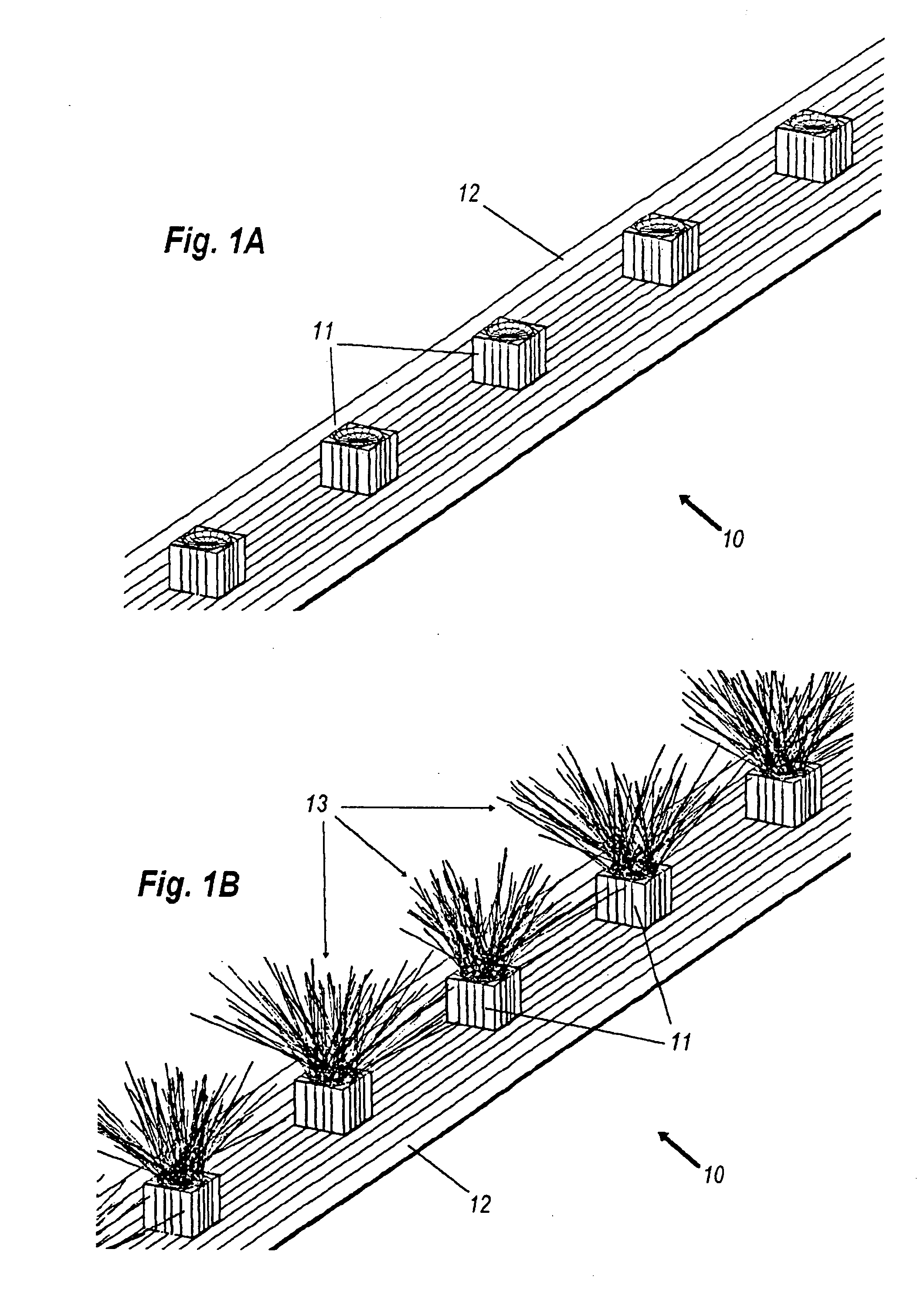
[0039] A Lambertian light source presents constant luminance at all viewing angles, so that off-axis foreshortening of its flat output aperture gives a cosine dependence of intensity. FIG. 1 shows a schematic of LED tape system 10 with LEDs 11 on thin electrified tape 12. FIG. 1B shows same but also with short Monte Carlo ray-segments 13.

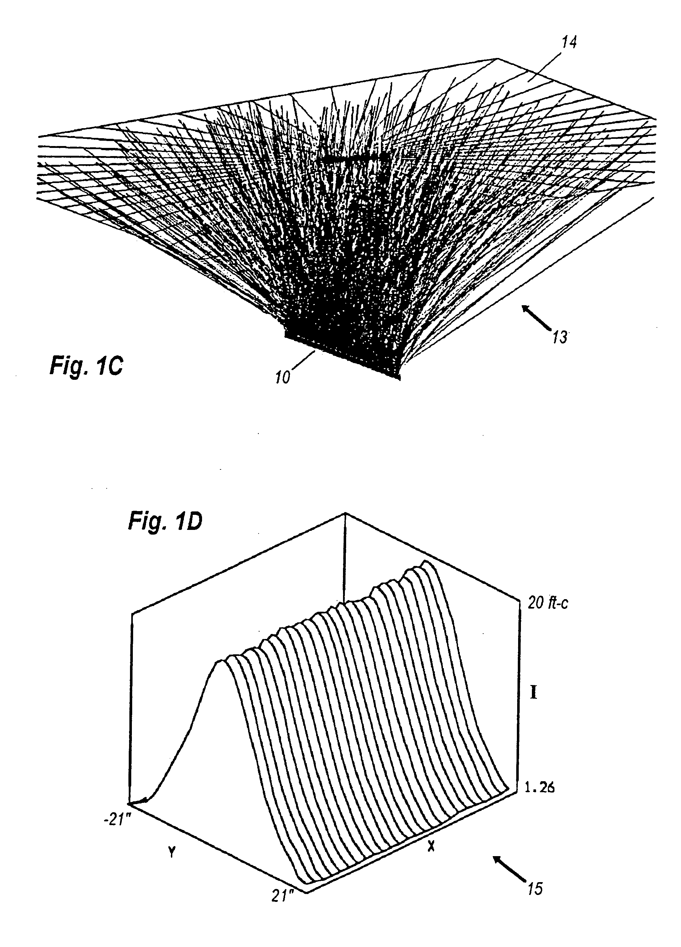
[0040]FIG. 1C shows tape system 10 emitting rays 13 that propagate out to target 14 at 1′ distance.

[0041]FIG. 1D shows 3-D illuminance plot 16 with height showing illuminance I in foot-candles across transverse dimension y of a target 1′ from the tape. As can be seen, illuminance has a central peak of 20 ft-c but is very dim at the edge, where incidence angle is 60°. Remedying this extreme nonuniformity is the object of the present invention.

[0042] Usually the intensity distribution of LEDs is given as a function of off-axis angle θ, with a circular distribution implicit. In the linear-lens case, however, the lateral off-axis angle a is for a lon...


PUM


Abstract

A cylindrical irradiance-redistribution lens is positioned over a line of LEDs, and is shaped to redistribute their light for uniformly illuminating a nearby planar target, such as shelves, signs, or walls. The lens shape is calculated via matching the cumulative lateral flux functions of the line of LEDs with that of the uniformly illuminated planar target. Numerous preferred embodiments are disclosed for a variety of illumination geometries.

Description

[0001] This application incorporates provisional application Ser. No. 60 / 646,617, filed Jan. 26, 2005.BACKGROUND OF THE INVENTION [0002] A prominent means of lighting long store-shelves is the fluorescent lamp, due to its low cost and good luminous efficacy. While the linear geometry of this lamp is appropriate for long shelves, its isotropic radiation pattern is not, because most of the light misses the target, unless bulky and expensive reflectors are employed. Also, the light that does make it to the shelf is not at all uniform. [0003] As their prices continue to fall, linear arrays of light-emitting diodes (LEDs) are becoming a viable alternative to fluorescent lamps, due to their longer life and greater compactness. Because LEDs radiate into a hemisphere (or less), optical lensing can be employed to distribute their light output. Such optics can be mounted individually on the LEDs, typically as domes. The prior art is deficient, however, in providing linear lenses for long arra...

Claims


Application Information

Patent Timeline
Patent Type & Authority Applications(United States)
IPC IPC(8): F21V1/00F21V11/00
CPCF21S4/008F21V5/04F21W2131/103F21Y2101/02F21Y2103/003G02B3/06G02B27/0911G02B27/095G02B27/0966G09F13/00G09F13/02G09F13/22G02B19/0066G02B19/0014F21S4/28F21Y2103/10F21Y2115/10
Inventor PARKYN, WILLIAM A.PELKA, DAVID G.
Owner SEOUL SEMICONDUCTOR
Learn More