
Lighting apparatus and liquid crystal display

a liquid crystal display and lighting apparatus technology, applied in lighting and heating apparatus, planar/plate-like light guides, instruments, etc., can solve problems such as disadvantageous increases in costs, and achieve the effect of improving illumination

Inactive Publication Date: 2006-07-27
FUJITSU LTD +1
View PDF20 Cites 42 Cited by
  • Summary
  • Abstract
  • Description
  • Claims
  • Application Information

AI Technical Summary

Benefits of technology

[0007] An object of the present invention is to provide a lighting apparatus which has a uniform luminance distribution and is inexpensive, and a liquid crystal display including the lighting apparatus.
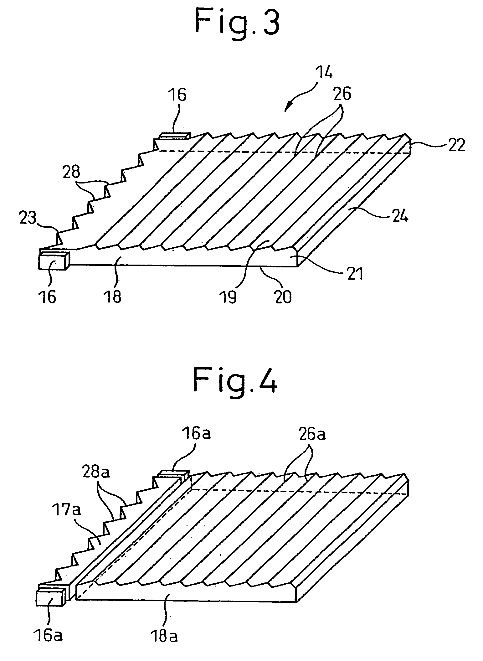
[0011] In the above-described structures, a plurality of prisms having the function of the linear light conductor are provided on one end surface of the planar light conductor, and the planar light conductor is integrated with the conventional linear light conductor, whereby the display quality, such as the luminance distribution, etc., is retained while the linear light conductor, which has been conventionally formed as a separate constituent part, is omitted to thereby decrease the number of the constituent parts to decrease the cost.
[0013] Furthermore, the planar light conductor has a groove or splits near the plural prisms, whereby the light totally reflected on the surface of the groove or the surfaces of the slits is deflected by the plural prisms, whereby the light incident on the planar light conductor can be effectively utilized, and the luminance can be improved.

Problems solved by technology

Accordingly, the constituent parts are many, and the steps of the fabrication are many, which disadvantageously increases the cost

Method used


Image

  • Lighting apparatus and liquid crystal display
  • Lighting apparatus and liquid crystal display
  • Lighting apparatus and liquid crystal display

Examples


Embodiment Construction

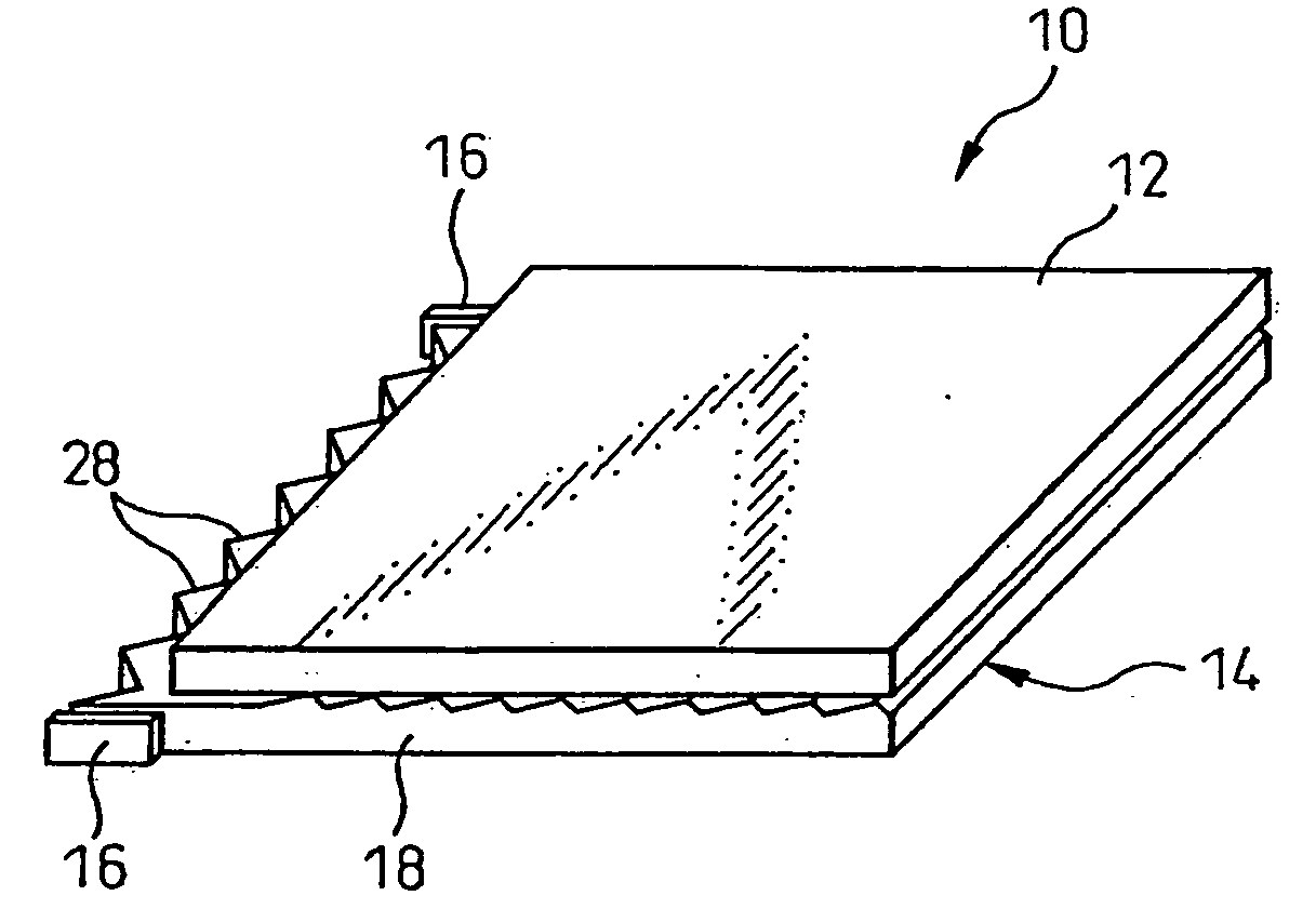
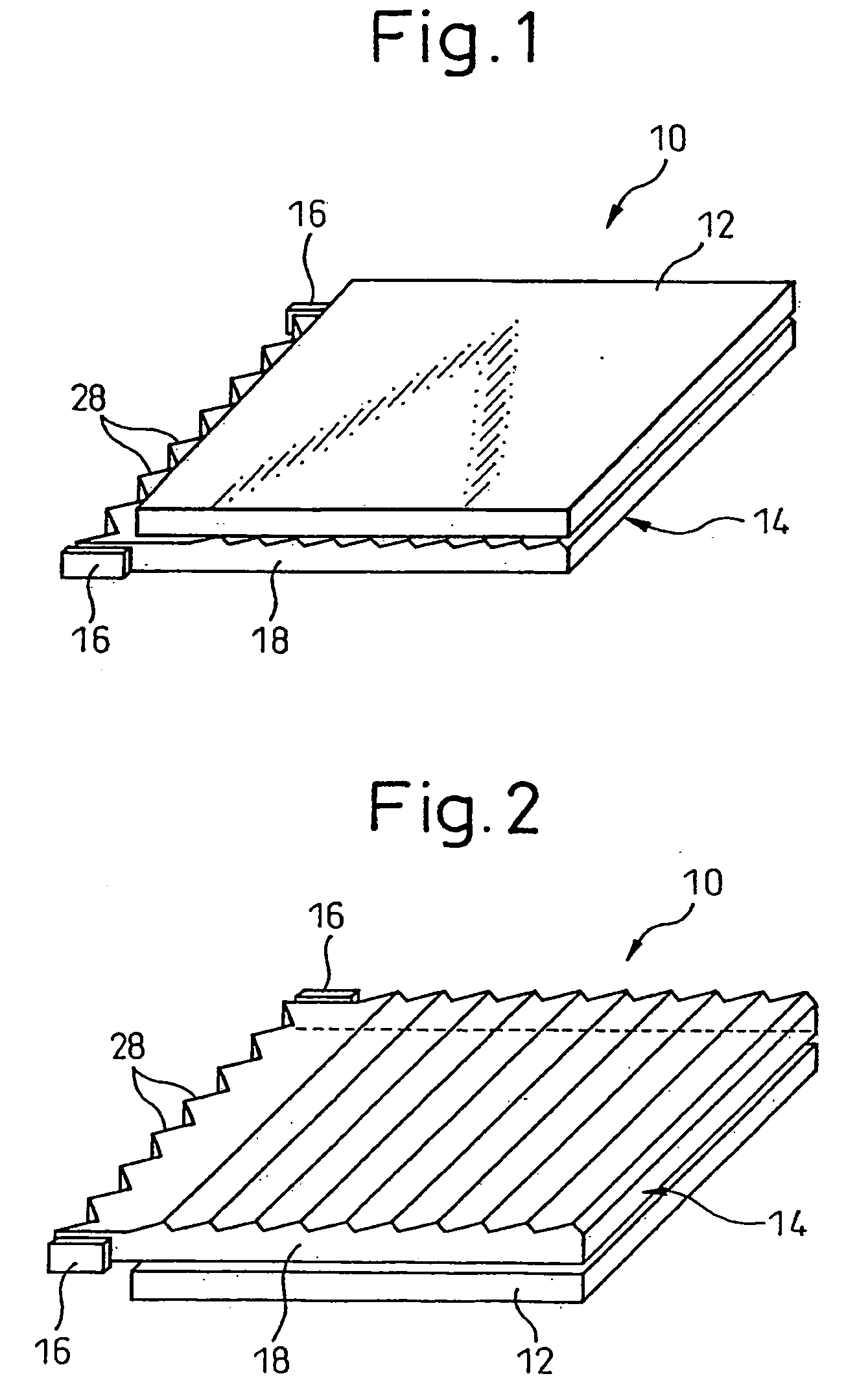
[0041]FIG. 1 is a perspective view of a liquid crystal display including the back light according to an embodiment of the present invention. The liquid crystal display 10 includes a liquid crystal panel 12, and a lighting apparatus 14 arranged on the side of the back of the liquid crystal panel 12. The liquid crystal panel 12 includes a liquid crystal sealed in a pair of glass substrates, and polarizers arranged on both sides of the liquid crystal panel 12. In this case, light of the lighting apparatus 14 passes through the liquid crystal panel 12 and arrives at a viewer.

[0042]FIG. 2 is a perspective view of a liquid crystal display including a front light according to an embodiment of the present invention. The liquid crystal display 10 includes a liquid crystal panel 12, and a lighting apparatus 14 arranged on the side of the front side of the liquid crystal panel 12. The liquid crystal panel 12 is a reflective liquid crystal panel having a reflection film, and the light of the l...


PUM


Abstract

The lighting apparatus comprises light sources (16) and a planar light conductor (18). The planar light conductor (18) includes opposed surfaces, side surfaces and end surfaces, and a plurality of prisms (28) are provided on one of the end surfaces (23). Said a plurality of prisms (28) have the function of the linear light conductor and provides a solid planar light conductor. The configuration of said plurality of prisms (28) is varied in accordance with positions thereof. The light source (16) is arranged so that the light is incident from position near the end surface. One of the opposed surfaces has means (26) for causing the light propagating inside the planar light conductor to exit from said one of the surfaces. The side surfaces or the bottom surface of the planar light conductor has slit (30, 32) or a groove (34). The liquid crystal display includes the lighting apparatus.

Description

CROSS REFERENCE TO RELATED APPLICATION [0001] This application is a Continuation of International Application No. PCT / JP03 / 10315, with an international filing date of Aug. 13, 2003, which designated the United States of America.TECHNICAL FIELD [0002] The present invention relates to a lighting apparatus and a liquid crystal display. BACKGORUND ART [0003] Liquid crystal displays, which are thin and light, are widely used as displays of portable information terminals. Liquid crystal itself is a light-receiving device which does not radiate by itself and includes a lighting apparatus for lighting the liquid crystal panel. The liquid crystal display is classified in transmitting liquid crystal display and the reflective liquid crystal display. The transmitting liquid crystal display has a lighting apparatus (back light) arranged on the side of the back, and the reflective liquid crystal display has a lighting apparatus (front light) arranged on the front side. The sunlight or light of r...

Claims


Application Information

Patent Timeline
Patent Type & Authority Applications(United States)
IPC IPC(8): F21V7/04F21V8/00
CPCG02B6/0018G02B6/0028G02B6/0038
Inventor MAEDA, SATOSHIARITAKE, HIROKAZU
Owner FUJITSU LTD
Learn More