Camera, control method therefor, program, and storage medium

a control method and camera technology, applied in the direction of exposure control, camera focusing arrangement, printers, etc., can solve the problems of difficult to know whether the defocus arises from a near-focus state or a far-focus state, and the contrast af focus detection is not suitable for a system, so as to increase the focusing speed and quickly focus the camera

Active Publication Date: 2006-07-27
CANON KK
View PDF6 Cites 41 Cited by
  • Summary
  • Abstract
  • Description
  • Claims
  • Application Information

AI Technical Summary

Benefits of technology

[0015] The present invention has been made to overcome the conventional drawbacks, and has as its object to increase the focus

Problems solved by technology

For example, contrast AF focus detection has a small detectable defocus amount, and it is difficult to detect the focus when the camera is greatly out of focus.
Contrast AF focus detection is not suitable for a system which requires quick operation or photographing an object which moves quickly.
Further, since the high-frequency component le

Method used


Image

  • Camera, control method therefor, program, and storage medium
  • Camera, control method therefor, program, and storage medium
  • Camera, control method therefor, program, and storage medium

Examples


first embodiment

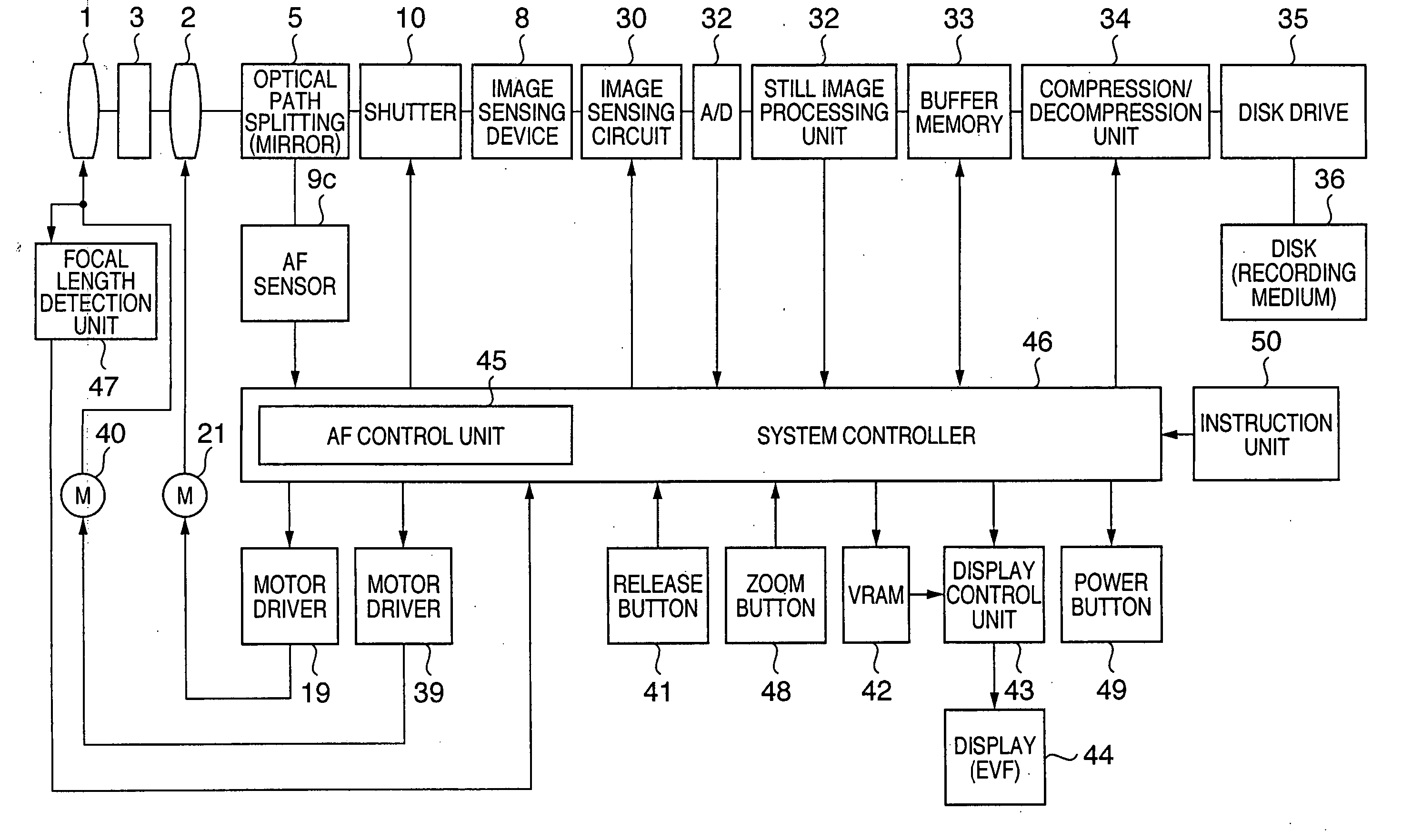
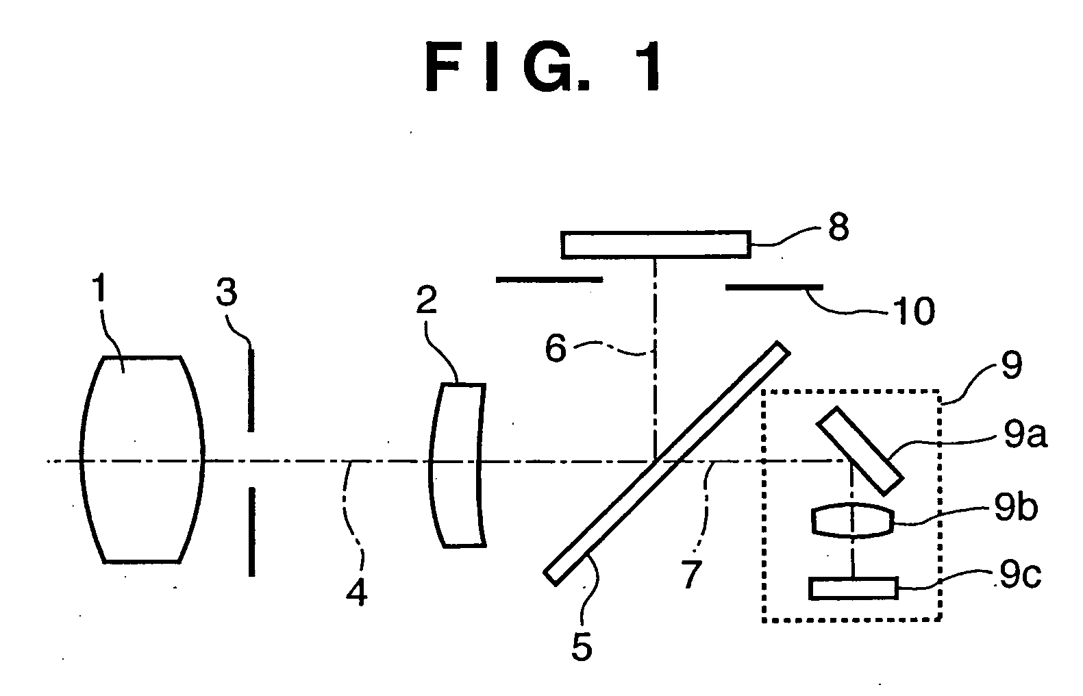
[0037]FIG. 1 is a view showing the configuration of an electronic camera according to the first embodiment of the present invention.

[0038] In FIG. 1, reference numerals 1 and 2 denote photographing lenses for photographing an object. Especially, the photographing lens 2 is a focus lens which is driven in focusing (focus adjustment). Reference numeral 3 denotes a stop which adjusts the light quantity of an object in accordance with the brightness of the object. Reference numeral 4 denotes a photographing optical axis of the photographing lens 1 and focus lens 2. Reference numeral 5 denotes an optical path splitting device which splits a light beam having passed through the photographing lens 1 and focus lens 2 into a photographing light beam and a light beam toward an AF (Auto Focus) system. The optical path splitting device 5 is a half-mirror according to the first embodiment. Reference numerals 6 and 7 denote a photographing optical axis and AF optical axis, respectively, serving ...

second embodiment

[0076] Only the difference of the second embodiment from the first embodiment will be explained.

[0077] In FIG. 12, the same step numerals denote the same operations as those of the first embodiment in FIG. 6, and a description thereof will be omitted.

[0078] In FIG. 12, step S105 is added between steps S2 and S3. In step S105, the camera user instructs in advance the camera on the position of a main object. The second embodiment adopts an instruction unit which allows the camera user to instruct in advance the camera on the position of a main object. That is, the camera user indicates an object with an instruction unit 50 while seeing the object on a display 44.

[0079] Steps S100 to S103 in FIG. 12 will be described. If the position of a main object does not fall within the phase difference AF area in step S8, a distance measurement point to be referred to must be determined, in order to refer to distance measurement information in phase difference AF near the position of the main ...


PUM


Abstract

This invention can increase the focusing speed and quickly focus a camera to an object regardless of the position of the object within the field of the viewfinder. When the position of a main object falls within a range in which phase difference AF is impossible, the lens scan range of contrast AF is determined by referring to distance measurement information of phase difference AF near the main object or immediately preceding distance measurement information of phase difference AF. The scan range of contrast AF is narrowed to increase the focusing speed.

Description

FIELD OF THE INVENTION [0001] The present invention relates to a focus control technique for a camera. BACKGROUND OF THE INVENTION [0002] Recently, so-called electronic cameras have prevailed. In the electronic camera, an object image is formed on a semiconductor image sensing device, e.g., an image sensor via a photographing optical system. The object image is converted into an electrical signal, and image data of the obtained still image is recorded on a recording medium such as a semiconductor memory or magnetic disk. [0003] Most electronic cameras of this type have an auto focus (AF) mechanism of controlling photographing conditions in order to automatically focus on an object image. The AF mechanism often adopts a method called contrast AF or hill-climbing AF. This is because the AF method can use an output from an image sensing device directly for AF. More specifically, in contrast AF, the contrast value (AF evaluation value) of a value output from an image sensing device is e...

Claims


Application Information

Patent Timeline
IPC IPC(8): G03B13/34
CPCG02B7/285G02B7/343G02B7/365G03B7/099G03B9/36H04N5/23212H04N23/672H04N23/673
Inventor ITO, KENJI
Owner CANON KK
Why Eureka
Try Eureka