Image forming apparatus, fixing apparatus, toner, and method of preparing toner

a technology of fixing apparatus and forming apparatus, which is applied in the direction of electrographic process apparatus, instruments, electrographic process, etc., can solve the problems of low fluidity and transferability, quick increase in temperature of fixing belt, staining and damaging recording medium,

Active Publication Date: 2006-07-27
RICOH KK
View PDF27 Cites 73 Cited by
  • Summary
  • Abstract
  • Description
  • Claims
  • Application Information

AI Technical Summary

Benefits of technology

[0023] This specification describes a novel image forming apparatus. In an example embodiment of the present invention, the novel image forming apparatus includes an image forming mechanism and a fixing mechanism. The image forming mechanism is configured to form a visible image using toner on a recording sheet according to input image data. The fixing mechanism is configured to fix the visible image onto the recording sheet. The fixing mechanism includes a first roller, a second roller, a belt, a third roller, and/or an applicator. The first roller is configured to rotate. The second roller includes inside a first ...

Problems solved by technology

The two heaters respectively heat the inner and outer circumferential surfaces of the fixing belt, resulting in quick increase in temperature of the fixing belt.
However, when a large amount of toner particles is adhered to the cleaning member, the toner particles may melt onto the fixing belt, resulting in staining and damaging the recording medium.
The toner particles produced in the mixing-kneading-pulverizing method generally have no definite shape, and have a broad particle size distribution, a low fluidity and transferability, a high fixing energy, a charging amount varying depending on toner particles, and a low charging stability.
An image formed with such toner particles may provide insufficient image quality.
However, the toner particles produced in the polymerization method have problems.
However, physical properties of the toner particles produced in the polymerization method are not sufficient.
In the polymerization method, it is not easy to control (e.g., vary) a shape of the toner particles.
Monomers for a binder (e.g., a binder resin) used in the suspension polymerization method may be limited to a styrene monomer and an acrylic monomer harmful to humans.
Toner particles produced in the suspension polymerization method contain those monomers and may cause environmental problems.
However, the toner particles produced in the suspension polymerization method have a lower fixing performance than the toner particles produced in the mixing-kneading-pulverizing method.
In the suspension polymerization method, the wax contained inside the toner part...

Method used


Image

  • Image forming apparatus, fixing apparatus, toner, and method of preparing toner
  • Image forming apparatus, fixing apparatus, toner, and method of preparing toner
  • Image forming apparatus, fixing apparatus, toner, and method of preparing toner

Examples


Embodiment Construction

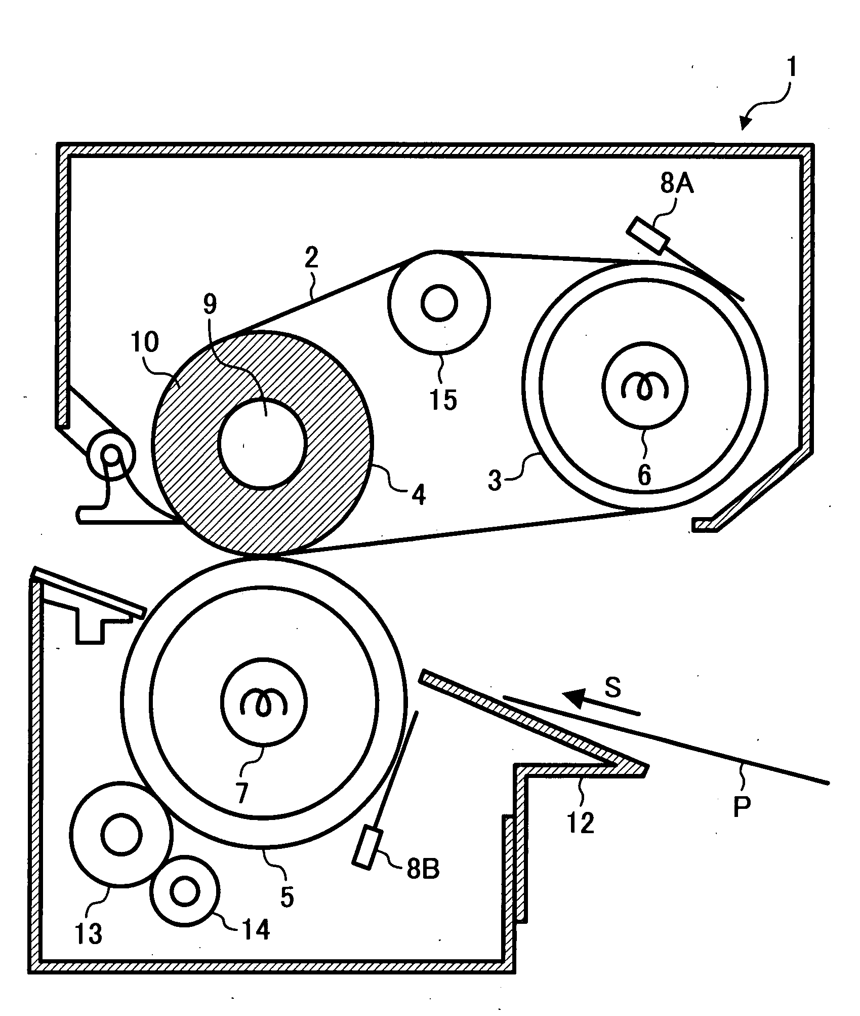
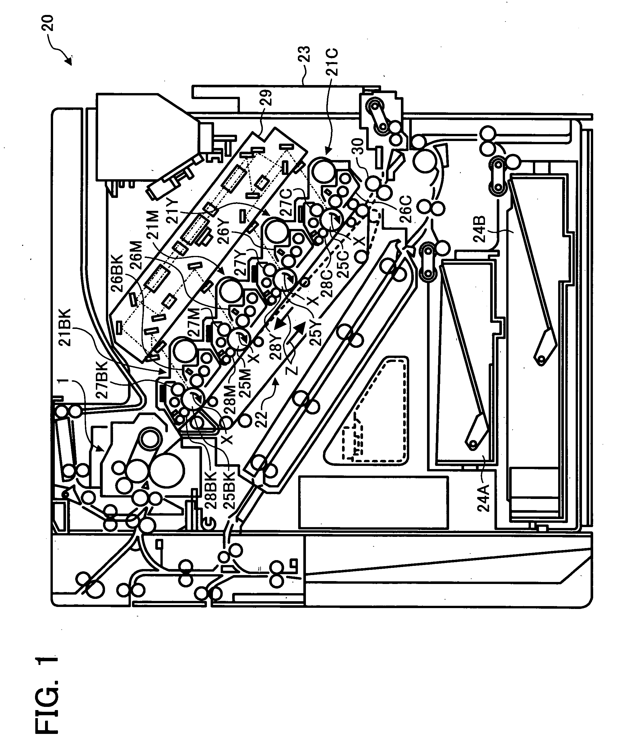
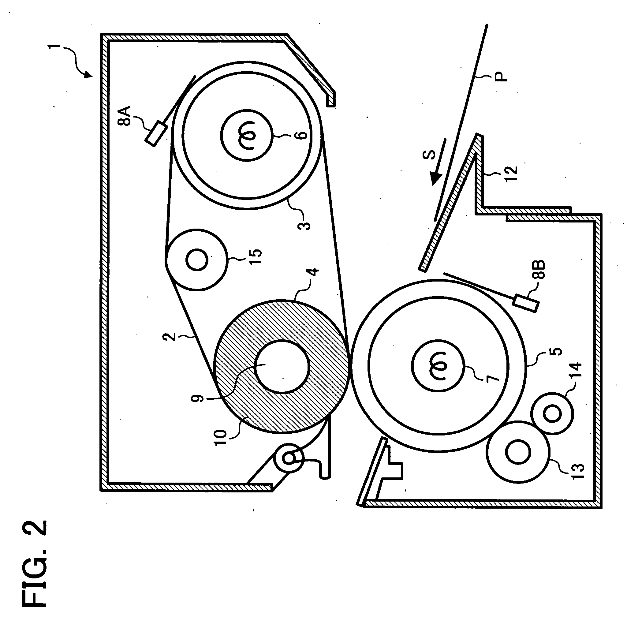
[0030] In describing example embodiments illustrated in the drawings, specific terminology is employed for the sake of clarity. However, the disclosure of this patent specification is not intended to be limited to the specific terminology so selected and it is to be understood that each specific element includes all technical equivalents that operate in a similar manner. Referring now to the drawings, wherein like reference numerals designate identical or corresponding parts throughout the several views, particularly to FIG. 1, an image forming apparatus according to an example embodiment of the present invention is explained.

[0031] As illustrated in FIG. 1, an image forming apparatus 20 includes an exposure unit 29, image forming units 21C, 21Y, 21M, and 21BK, a bypass tray 23, paper trays 24A and 24B, a registration roller 30, a transfer unit 22, and / or a fixing unit 1.

[0032] The image forming unit 21C includes a charger 27C, a photoconductive drum 25C, a development unit 26C, a...


PUM

PropertyMeasurementUnit
Angleaaaaaaaaaa
Lengthaaaaaaaaaa
Lengthaaaaaaaaaa

Abstract

An image forming apparatus includes an image forming mechanism and a fixing mechanism. The fixing mechanism fixes a visible image formed by the image forming mechanism onto a recording sheet. The fixing mechanism includes a first roller, a second roller, a belt, a third roller, and an applicator. The second roller includes a first heater having a first heat capacity. The belt is looped over the first and second rollers. The third roller is arranged opposite to the first roller via the belt, includes a second heater having a heat capacity smaller than the first heat capacity of the first heater, applies a pressure to the belt and the first roller, and rotates in conjunction with a movement of the first roller via the belt. The applicator is arranged at a position in contact with the third roller and applies oil to a surface of the third roller.

Description

CROSS-REFERENCE TO RELATED APPLICATION [0001] The present application is based on and claims priority to Japanese patent application No. 2005-014948 filed on Jan. 24, 2005 in the Japan Patent Office, the entire contents of which are hereby incorporated herein by reference. BACKGROUND OF THE INVENTION [0002] 1. Field of the Invention [0003] Example embodiments of the present invention relate to an image forming apparatus, a fixing apparatus, a toner, and a method or preparing a toner. [0004] 2. Description of the Background Art [0005] Methods for forming an image by developing an electrostatic latent image in an image forming apparatus, for example, electrophotographic and electrostatic recording methods, are now used in various fields. In the electrophotographic method, an electrostatic latent image is formed on a photoconductor based on image data through charging and exposing processes. The electrostatic latent image is developed with a developer into a toner image and transferred...

Claims


Application Information

Patent Timeline
IPC IPC(8): G03G15/20
CPCG03G9/0806G03G9/08755G03G9/08791G03G9/08793G03G9/08795G03G9/08797G03G2215/2016G03G2215/2032G03G2215/2093G03G15/2025G03G15/2028G03G15/2064
Inventor YOSHINAGA, HIROSHINAMEKATA, SHINICHISHIMADA, HIROYUKIEHARA, MASANAOOGAWA, HIROFUMIOGAWA, TADASHIFUJIMOTO, IPPEL
Owner RICOH KK
Why Eureka
Try Eureka