Structure of intermediate wall of three arch excavated tunnel and method for constructing the same

a technology of three arch excavating tunnels and intermediate walls, which is applied in the direction of mining structures, shaft equipment, shaft linings, etc., can solve the problems of whitening the surface of the area, requiring an excessively large area for constructing the tunnel, and reducing the stability of the pillars

Inactive Publication Date: 2006-07-27
DONG HYUNG SEO
View PDF1 Cites 26 Cited by
  • Summary
  • Abstract
  • Description
  • Claims
  • Application Information

AI Technical Summary

Benefits of technology

[0031] In accordance with still yet another aspect of the present invention, there is provided a method for constructing an intermediate wall of a three arch excavated tunnel, in which through holes are formed for damping vibration before left and right main tunnels are excavated by blasting, thus preventing the ground around a ceiling portion of the intermediate wall from being damaged when the left and right main tunnels are excavated by blasting.

Problems solved by technology

Further, there have been required designs of the roads for minimizing right of way in order to meet recent requirements of a tunnel having a large cross-section and increased price of land.
A conventional tunnel having total four lanes is designed such that an up-tunnel and a down-tunnel are spaced from each other by a distance of 30 m or more in consideration of arching of an original ground, thus requiring an excessively large area for constructing the tunnel.
The pillars have a reduced stability due to water leakage from a ceiling area of the tunnel and the occurrence of freezing in the winter season.
These phenomena occur due to failure of drainage at a low point of an upper end of an intermediate area of the two main tunnels.
However, the subterranean water is gathered in low-level areas (low points) of the ceiling area and is not easily drained, thus generating subterranean water leakage and whitening the surface of the areas.
Thus, the conventional tunnel is disadvantageous in that the number of constructing steps is increased and a long construction period is taken.
Further, since the pillars of the conventional tunnel are separated from the ceiling area by a waterproof layer, the pillars are fixed to the tunnel not by hinges or fixing points but by free terminals and the filling of a grout material is incompletely performed.
As shown in FIG. 2b, which is an assembled cross-sectional view of reinforcing bars of an intermediate wall of a conventional three arch excavated tunnel, construction of clamp joint steels between the intermediate wall and lining concrete causes complexity in installing a mold and placing concrete and a difficulty in construction, thus deteriorating quality of the pillars when the concrete is placed.
Further, when main tunnels of the conventional tunnel are excavated by blasting, a vibration damping method for protecting the ground located at top portions of the pillars is not applied.
Accordingly, the excavation of the conventional tunnel easily damages the ground.

Method used


Image

  • Structure of intermediate wall of three arch excavated tunnel and method for constructing the same
  • Structure of intermediate wall of three arch excavated tunnel and method for constructing the same
  • Structure of intermediate wall of three arch excavated tunnel and method for constructing the same

Examples


Embodiment Construction

[0061] Now, preferred embodiments of the present invention will be described in detail with reference to the annexed drawings. However, the following description does not limit the subject matter of the present invention.

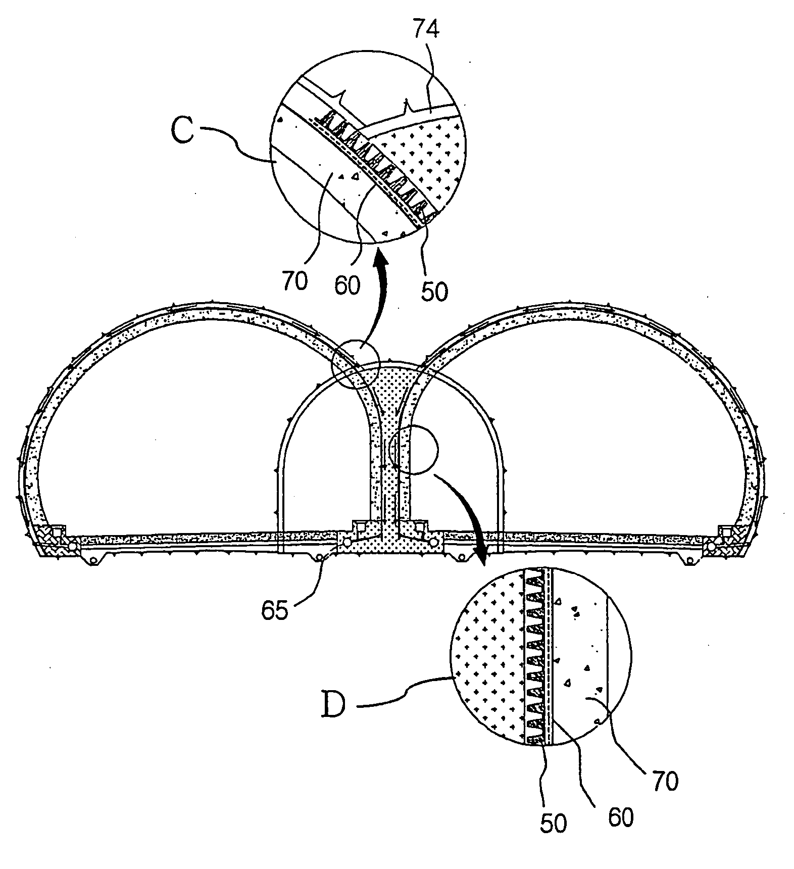
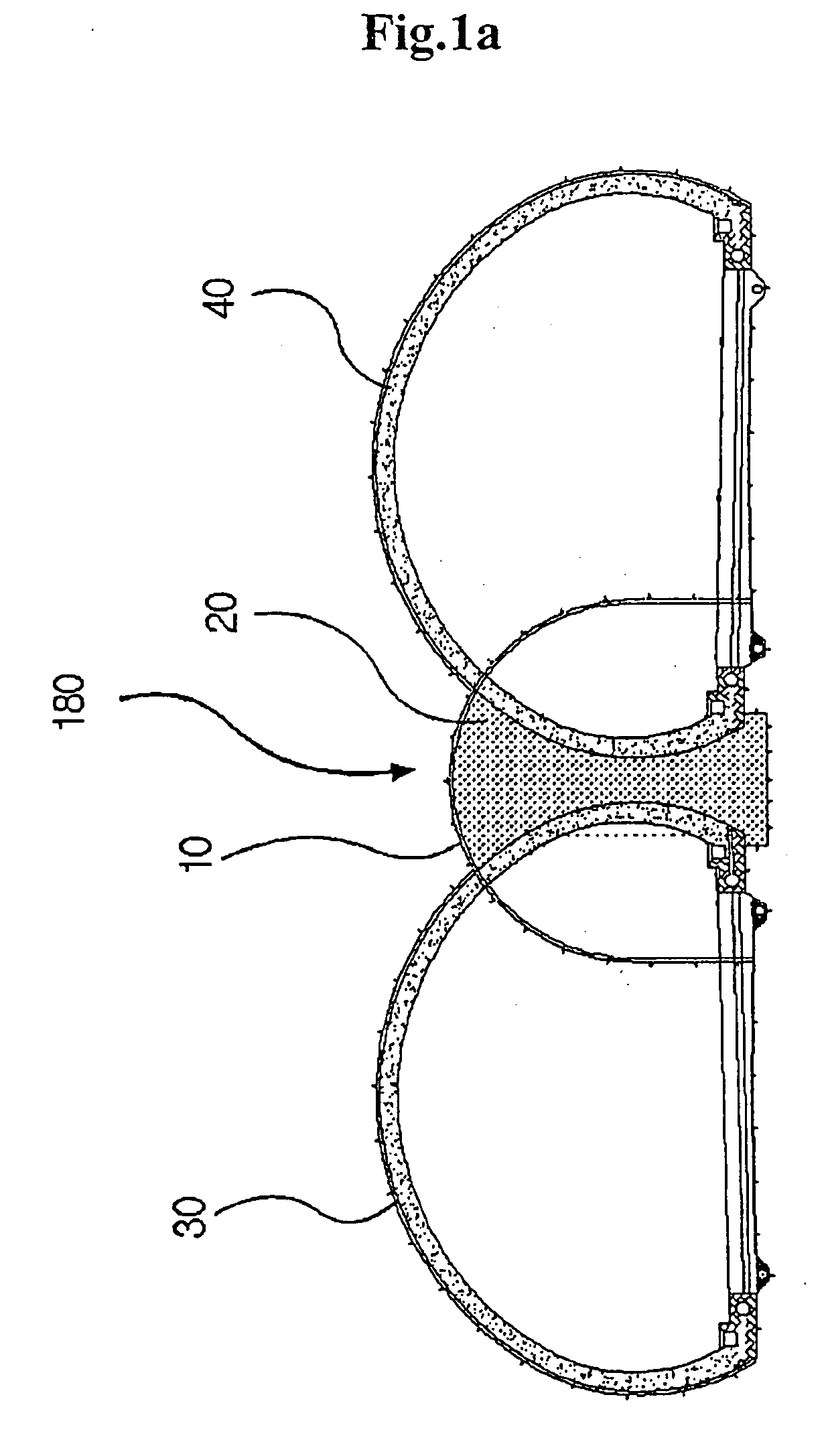
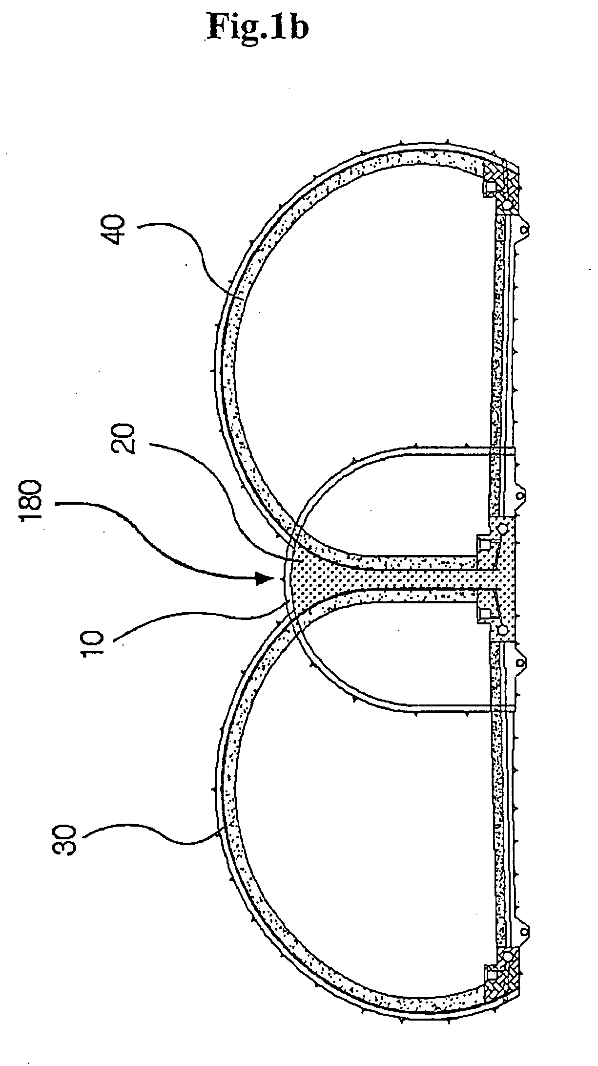
[0062]FIGS. 1a and 1b illustrate a three arch excavated tunnel constructed by a method in accordance with the present invention. As shown in FIG. 3, a method for constructing the three arch excavated tunnel sequentially comprises a step 131 for excavating an upper portion of a central tunnel 10, a step 132 for excavating a lower portion of the central tunnel 10, a step 133 for forming an intermediate wall 20 by assembling reinforcing bars passing through the central tunnel 10 and by placing concrete therein, and grouting a gap formed on an upper end of the intermediate wall 20 and a ceiling portion of the central tunnel 10, a step 134 for excavating an upper portion of a left main tunnel 30, a step 135 for excavating an upper portion of a right main tunnel 40, a st...


PUM


Abstract

Disclosed are a structure of an intermediate wall of a three arch excavated tunnel, which effectively exhausts subterranean water from a peripheral ground, and a method for constructing the tunnel. The method comprising the steps of: (a) excavating an upper portion of a central tunnel 10; (b) excavating a lower portion of the central tunnel 10; (c) forming an intermediate wall 20 and grouting a gap formed in the intermediate wall 20; (d) excavating an upper portion of a left main tunnel 30; (e) excavating an upper portion of a right main tunnel 40; (f) excavating a lower portion of the left main tunnel 30; (g) excavating a lower portion of the right main tunnel 40; and (h) installing a drain board 50 and a waterproof layer 60 and casting lining concrete 70 therein so that the tunnel is easily drained through drain pipes 65 and residual water pressure is eliminated.

Description

TECHNICAL FIELD [0001] The present invention relates to a structure of an intermediate wall of a three arch excavated tunnel for subways, trains or roads in downtown areas, in which a plurality of main tunnels are close to each other and through holes are formed through the tunnel so as to reduce damage to the intermediate wall and the ground round when main tunnels are excavated by blasting, and a method for constructing the same, thus reducing a tapered length between a start point and an end point of the subways, trains or roads so that the linearity of the subways, trains or roads is improved, reducing an area of a site for the subways, trains or roads so that economic efficiency of construction is improved, solving a difficulty and a drainage problem caused by a conventional two arch tunnel, and fixedly connecting the intermediate wall to the ground around a ceiling of the tunnel so that the stability of structure is increased. BACKGROUND ART [0002] Recently, large-scaled roads...

Claims


Application Information

Patent Timeline
Patent Type & Authority Applications(United States)
IPC IPC(8): E21D11/00E21D9/00E21D9/14E21D11/38E21F16/02
CPCE21D9/006E21D9/14E21D11/38E21F16/02E21D9/00
Inventor SEO, DONG-HYUNYUN, SEOK-RYULKWON, OH-HYUN
Owner DONG HYUNG SEO
Why Eureka
Try Eureka