Retroreflective functional member and retroreflecting unit

Inactive Publication Date: 2006-07-27
TSUTSUI OSAMU
View PDF3 Cites 12 Cited by
  • Summary
  • Abstract
  • Description
  • Claims
  • Application Information

AI Technical Summary

Benefits of technology

[0047] By selecting laminated retroreflective function members having different retroreflective properties, for example, by increasing the number of lens bodies used for a long distance, it is possible to drastically improve the visibility at a long distance of 300-400 m in night dri

Problems solved by technology

Then, non-uniformity of the glass bead in particle diameter affects the reflective efficiency.
However, it is considered that the reflective efficiency is reduced by about 22% due to the non-uniformity of the particle diameter compared with using the beads of which the particle diameters are the same and ideal.
However, as far as performance is concerned, their prototype models are still in s

Method used


Image

  • Retroreflective functional member and retroreflecting unit
  • Retroreflective functional member and retroreflecting unit
  • Retroreflective functional member and retroreflecting unit

Examples


Embodiment Construction

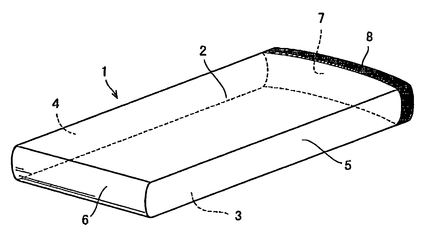
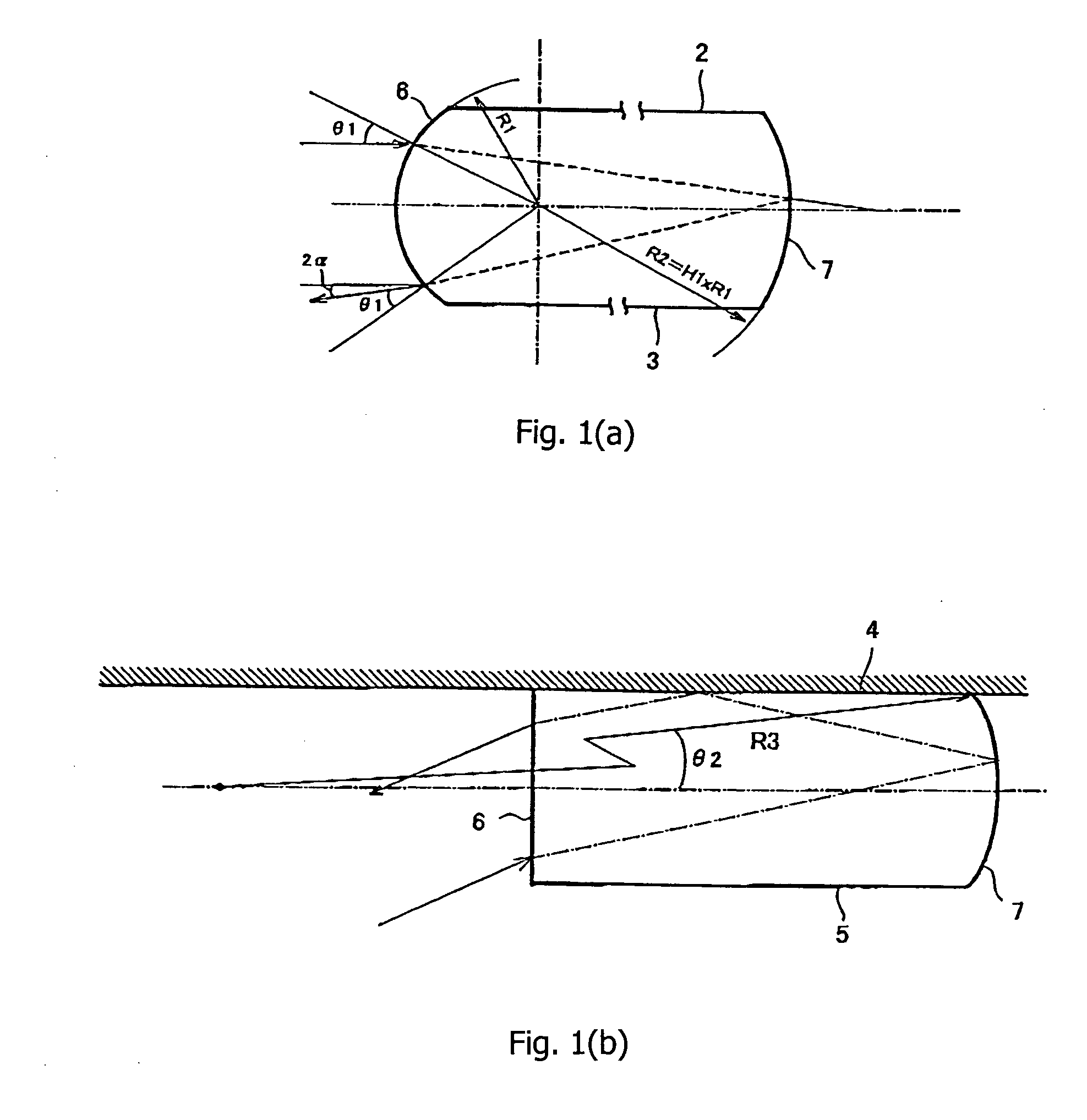
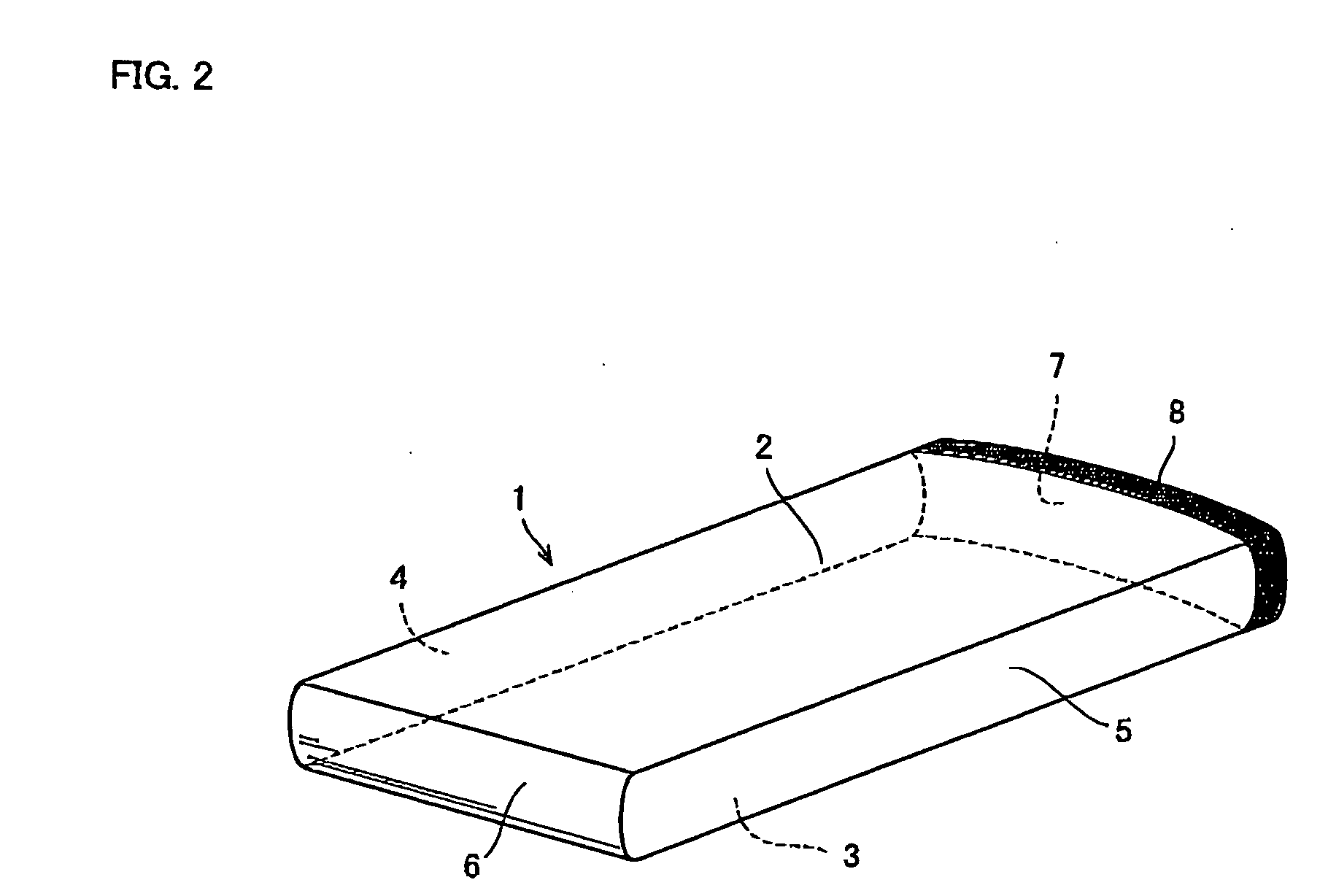
[0078] Preferred embodiments of the present invention will now be described with reference to the accompanying drawings. FIG. 2 is a perspective view of a retroreflective function member according to the present invention. FIG. 3(a) is a side view of the retroreflective function member according to the present invention, FIG. 3(b) is a plan view of the retroreflective function member according to the present invention, and FIG. 3(c) is a plan view of another embodiment.

[0079] A retroreflective function member 1 is formed by injection molding the transparent acrylic resin and is substantially plate-shaped, in which the upper surface 2, the lower surface 3, and right and left side surfaces 4 and 5 are formed flat. The front surface 6 is the incident (incoming) and outgoing surface, the rear surface 7 is aluminum-deposited to serve as a reflected surface, and the outside of the rear surface 7 is protected by a resin 8.

[0080] The side of the retroreflective function member 1 is not pa...


PUM

PropertyMeasurementUnit
Angleaaaaaaaaaa
Angleaaaaaaaaaa
Angleaaaaaaaaaa

Abstract

A retroreflective function member exhibits better retroreflective properties than a cube corner type retroreflective function member, which e has conventionally excelled most in the retroreflective properties is provided. The retroreflective function member is formed by injection molding transparent acrylic resin to provide a substantially plate-shape of which the upper surface, the bottom surface, and right and left surfaces are flat. The front surface is adapted to serve as the incoming and outgoing surfaces and aluminum is deposited on the rear surface to be used as a reflective surface. The outside of the rear surface is protected by a resin.

Description

FIELD OF INVENTION [0001] The present invention relates to a retioreflective function member which causes the incoming light to reflect toward a light source, and a retroreflective unit in which the retroreflective function members are laminated. More particularly, the present invention is directed to devices such as delineators of a guardrail on a highway, studs, signs used for marine salvage which are required to be visibly confirmed both at long and short distances. BACKGROUND OF THE INVENTION [0002] There is a micro-glass sphere type retroreflective function member and a cube corner type retroreflective function member in a retroreflective function member. [0003] Known for providing the micro-glass sphere type retroreflective function member are technology whereby glass beads are mixed with road traffic paint with the help of the glass beads' (lens) own retroreflective ability, a reflective cloth in which one surface of base cloth is provided with a paint layer containing glass ...

Claims


Application Information

Patent Timeline
IPC IPC(8): B32B23/02E01F9/524E01F9/553G02B5/126
CPCE01F9/06Y10T428/24777G09F13/16G02B5/126E01F9/553
Inventor TSUTSUI, OSAMU
Owner TSUTSUI OSAMU
Why Eureka
Try Eureka