Mathematical circulatory system model

a circulatory system and mathematical technology, applied in the field of mathematical circulatory system models, can solve the problems of inability of closed system models to incorporate the influence of important extracranial factors on intracranial pressure dynamics, unsuitable for studying multiple parameter changes, and the effect of interconnected subsystems on each other, and one of the main limitations of lumped-parameter approach

Inactive Publication Date: 2006-07-27
UNIVERSITY OF VERMONT
View PDF17 Cites 120 Cited by
  • Summary
  • Abstract
  • Description
  • Claims
  • Application Information

AI Technical Summary

Benefits of technology

[0011] In one embodiment, a method of modeling a circulatory system is provided. The method includes (a) providing a circulatory system model including one or more time-dependent pressure functions, each of the one or more time-dependent pressure functions representing a portion of the circulatory system; (b) using a logistic function to represent a regulatory mechanism parameter, the regulatory mechanism parameter representing a regulatory mechanism having an impact on circulatory system function; and (c) solving the logistic function and at least one of the one or more time-dependent pressure functions to determine a circulatory system value.

Problems solved by technology

However, the ability of these closed-system models to incorporate the influence of important extracranial factors on intracranial pressure dynamics is clearly limited.
As noted in prior art studies, the intracranial system involves a number of subsystems, which interact through complex mechanisms, and the classical piecewise approach, which often considers CSF dynamics separately, is not suited to studying multiple parameter changes and the effects of interconnected subsystems on each other.
This is one of the main limitations of the lumped-parameter approach.
However, clearly this subdivision process cannot be carried to an extreme as the resulting system of linked governing equations will rapidly become too large for practical analysis and solution.
However, despite not strictly abiding by the Kellie-Monro Doctrine, the first model falls far short of being a whole-body model for intracranial pressure dynamics.
For example, the first model fails to include representations for the extracranial physiology of the cardiovascular system and the tissues and extracellular fluids of both the central and lower body, including cardiovascular autoregulation, colloid osmotic pressure, and a lymphatic system.
In addition, the second model fails to include the external environment as an implicit compartment.

Method used


Image

  • Mathematical circulatory system model
  • Mathematical circulatory system model
  • Mathematical circulatory system model

Examples


Embodiment Construction

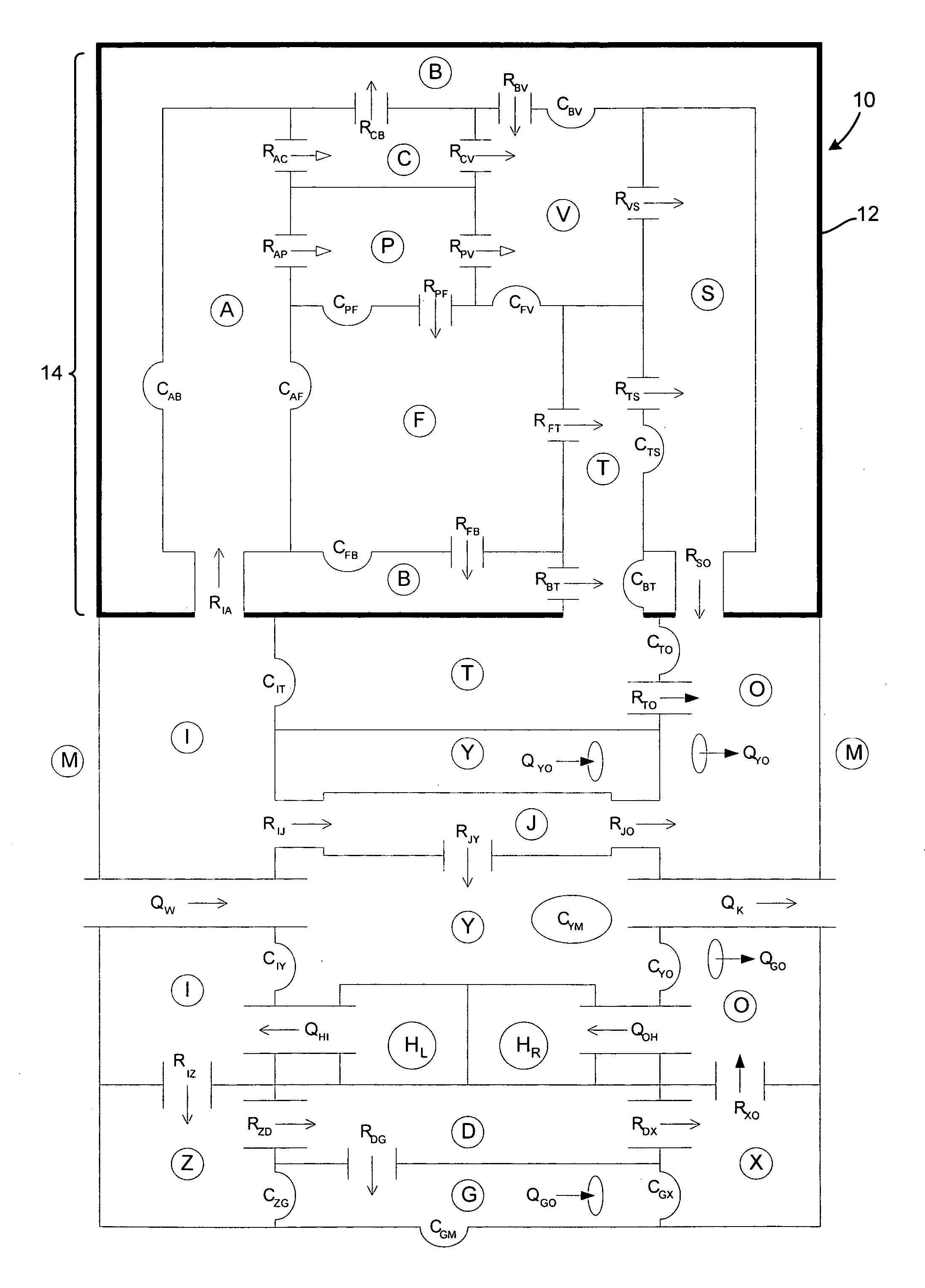
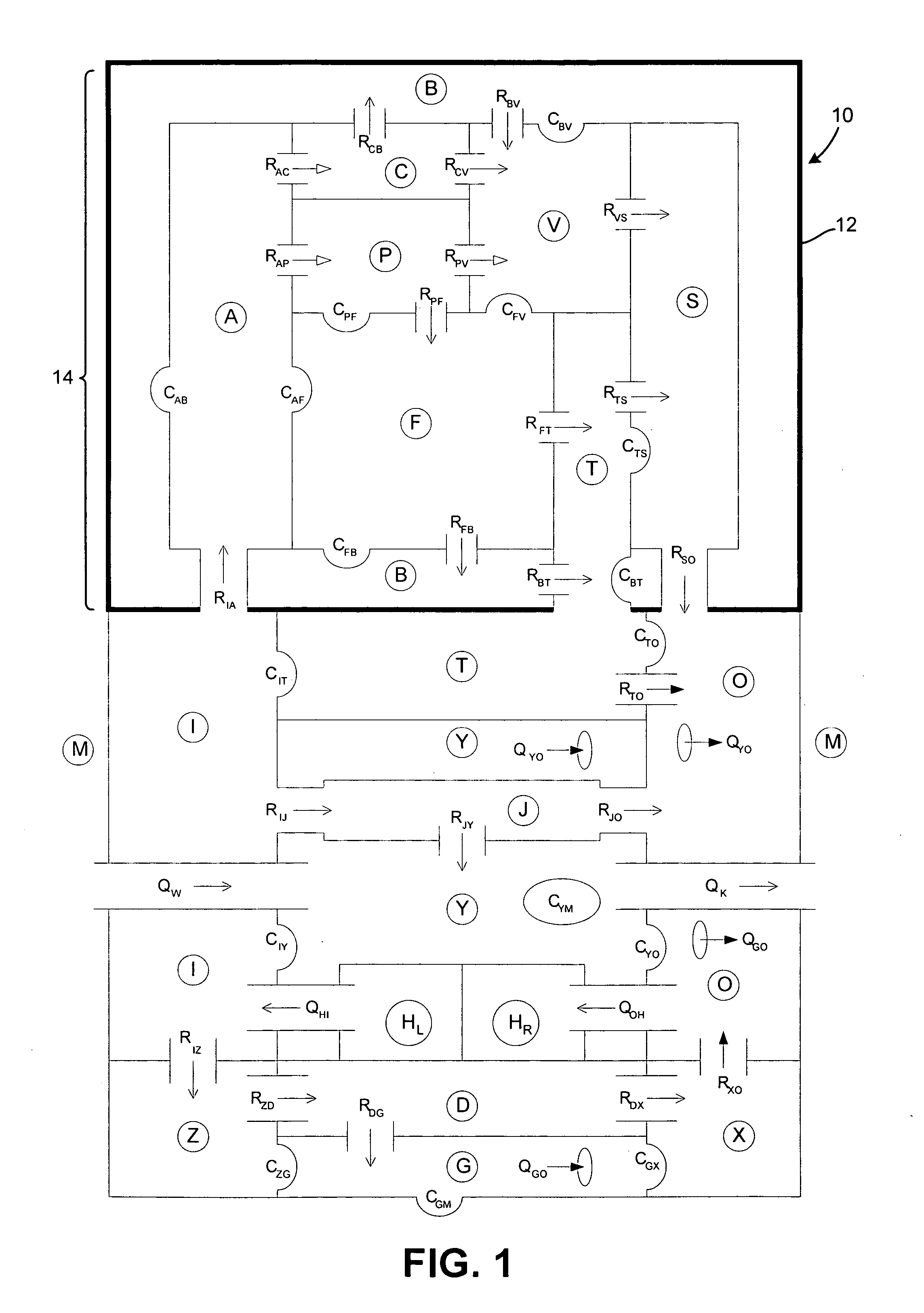
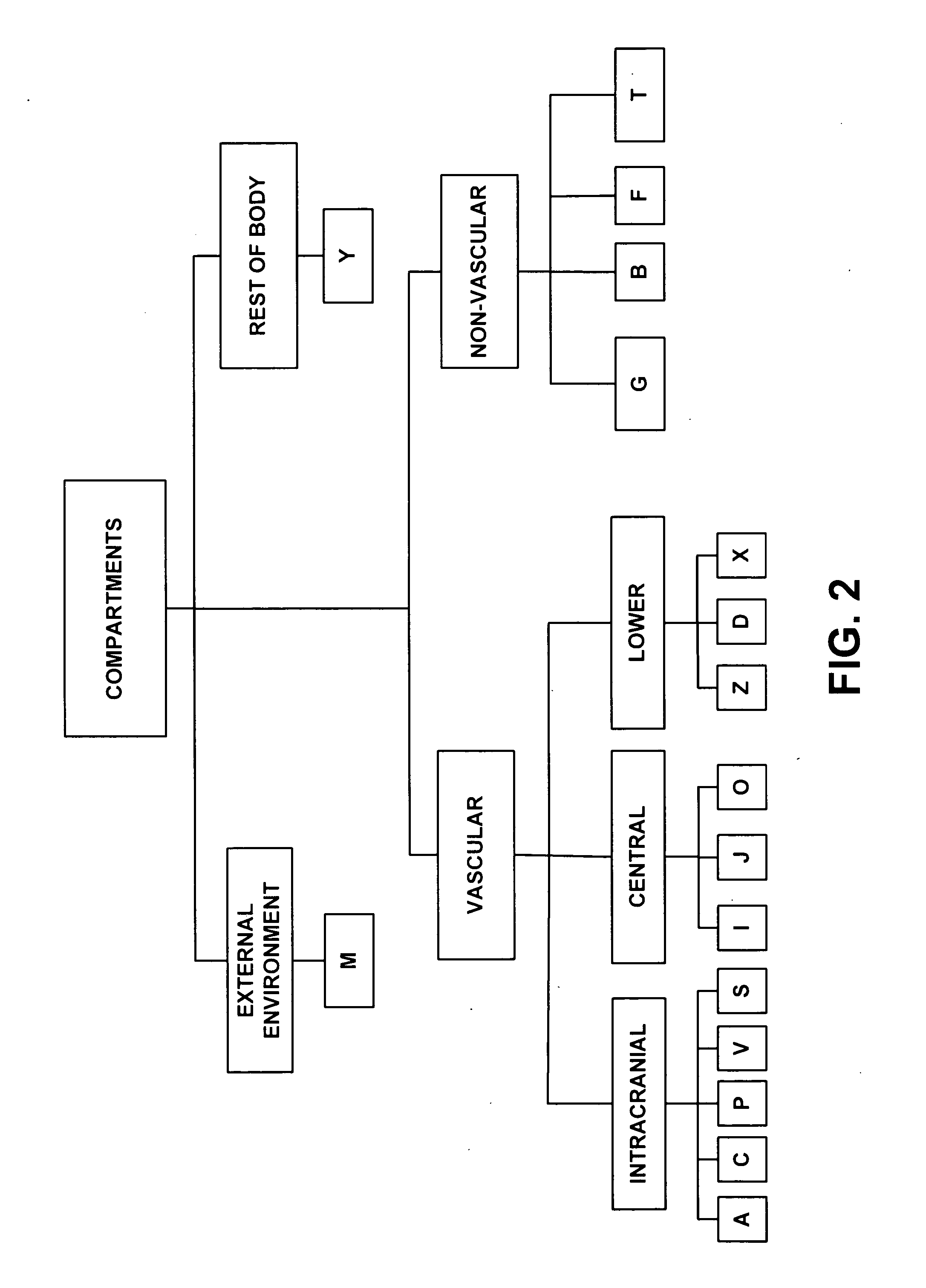
[0040] The present disclosure is directed to a mathematical circulatory system model. In one aspect, the system and method of the disclosure includes a lumped-parameter model utilizing one or more differential equations representing pressure dynamics. One exemplary embodiment of the present disclosure is set forth in greater detail below with reference to FIGS. 1 to 11. This first embodiment is directed to a whole-body mathematical model for simulating intracranial pressure dynamics. Another exemplary embodiment of the present disclosure is set forth in greater detail below with reference to FIGS. 12 to 21. This second embodiment is directed to a simplified mathematical circulatory system model simulating nervous system regulatory mechanisms.

Whole-Body Embodiment for Simulating Intracranial Pressure Dynamics

[0041] In one embodiment a whole-body mathematical model for simulating intracranial pressure dynamics is provided. As described in U.S. Provisional Patent Ser. No. 60 / 409,551...


PUM


Abstract

A system and method of modeling a circulatory system including a regulatory mechanism parameter. In one embodiment, a regulatory mechanism parameter in a lumped parameter model is represented as a logistic function. In another embodiment, the circulatory system model includes a compliant vessel, the model having a parameter representing a change in pressure due to contraction of smooth muscles of a wall of the vessel.

Description

RELATED APPLICATION DATA [0001] This application claims the benefit of U.S. Provisional Patent Application No. 60 / 664,723, filed Mar. 24, 2005, entitled “Mathematical Circulatory System Model.” This application is a continuation-in-part of, U.S. patent application Ser. No. 10 / 658,638, filed Sep. 9, 2003, entitled “Whole-Body Mathematical Model for Simulating Intracranial Pressure Dynamics,” which claims the benefit of U.S. Provisional Patent Application No. 60 / 409,551, filed Sep. 10, 2002, entitled “A Mathematical Model for Human Intracranial Pressure and Flow Dynamics,” and U.S. Provisional Patent Application No. 60 / 416,508, filed Oct. 7, 2002, entitled “A Mathematical Model for Human Intracranial Pressure and Flow Dynamics.” Each of these four prior applications are incorporated herein by reference in their entirety.GOVERNMENT LICENSE RIGHTS [0002] The U.S. Government may have a paid-up license in this invention and the right in limited circumstances to require the patent owner to...

Claims


Application Information

Patent Timeline
Patent Type & Authority Applications(United States)
IPC IPC(8): G09B23/28G06G7/48
CPCG06F19/3437G09B23/12G09B23/30G09B23/32G16H50/50
Inventor LAKIN, WILLIAM D.STEVENS, SCOTT A.
Owner UNIVERSITY OF VERMONT
Why Eureka
Try Eureka