
Methods and apparatus for intraoperative administration of analgesia

an analgesic and intraoperative technology, applied in the field of intraoperative administration of analgesics, can solve the problems of increasing local muscle spasms and even more pain, postoperative period has proven inability to prevent incisional area pain and/or leg pain from triggering the pain spasm cycle in the majority of patients, and superficial analgesics usually only provide incomplete pain managemen

Active Publication Date: 2006-07-27
SPINAL INTEGRATION
View PDF12 Cites 3 Cited by
  • Summary
  • Abstract
  • Description
  • Claims
  • Application Information

AI Technical Summary

Problems solved by technology

This combination often leads to the creation of a pain spasm cycle of the lumbar muscles at the incisional wound area where the local muscle spasms cause more incisional area pain, which then cause more local muscle spasms and even more pain.
This pain spasm cycle is not only quite uncomfortable to the patient but additionally prevent many patients with a smaller procedure such as a discectomy or laminoforaminotomy (typically the L4-L5 or L5-S1 level and occasionally the L3-L4 level) from going home on the day of surgery.
The current therapy of a combination of intravenous and oral medication in the postoperative period have proven unable to prevent the incisional area pain and / or leg pain from triggering the pain spasm cycle in the majority of patients.
However, this superficial analgesia usually only provides incomplete pain management because the deep wound musculature structures nor the ligaments around the facet joint and posterior longitudinal ligament are not covered by the superficial injection in the skin.
These deep structures cannot be adequately injected without risk of intradural injection.
An intradural injection can result in various medical problems including life threatening seizures and reversible paralysis sometimes requiring a ventilator for temporary support.
Additionally the total muscle that is surgically injured (painful in the postoperative period) is not only the muscle disconnected for the bone visually seen in the surgical incision but all the muscle stretched for the necessary surgical retraction.
This stretch injured muscle tissue can be over 2 inches from the surgical wound and hence difficult to completely block with a local injection.
The vast majority of Spinal Surgeons have been ineffective in using this form of postoperative pain management.
If a spinal injection is done in or near the operative site, there is always a risk of spinal fluid leak into the surgical defect.
If the spinal fluid leaked through the skin then meningitis with the risk of death can occur.
A separate puncture remote to the lumbar surgical incision has not been routinely used for postoperative pain management in an outpatient setting because of the risk of respiratory depression on a delayed basis.
However, epidural administration of analgesia via the lower lumbar surgical exposure after minimally invasive lumbar spine surgical procedures does present several technique challenges.
Threading an epidural catheter intra-operatively in via the small lumbar incision to the L1 to T10 region is difficult even with a guide wire.
Although the surgical identification of the epidural space is obvious intraoperatively, the catheter is threaded in a path that is at right angle to the surgical vision axis making it mechanically difficult to thread with the right angle bend necessary at the bottom of the wound.
Although it is possible to use an expensive CSF lumbar drainage catheter and advance it into this midline dorsal epidural space with a bayonet forceps, this technique is very cumbersome, technically demanding, time consumining, and requires extra midline bone removal.
Also in some cases it is impossible to thread the catheter especially in the small minimally invasive lumbar spinal wounds.
The threading difficulty of the epidural catheter via a lumbar surgical wound arises from the need to thread the catheter at the bottom of the wound at an essentially right angle to the line of sight of the small surgical wound.
The sharp angle of turn at the bottom of the wound combined with the catheter threading is beyond the surgical capability or patience of most spinal surgeons when current supplies and equipment are utilized.

Method used


Image

  • Methods and apparatus for intraoperative administration of analgesia
  • Methods and apparatus for intraoperative administration of analgesia
  • Methods and apparatus for intraoperative administration of analgesia

Examples


example 1

Intraoperative Administration of Analgesia

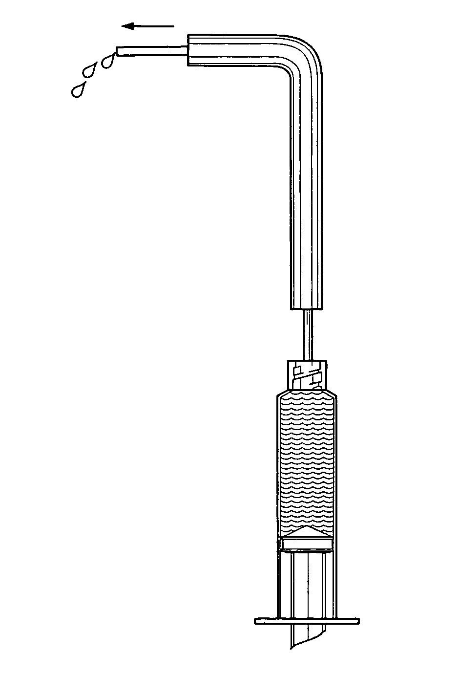
[0040] 1) A Kerrison punch is used to expose the midline fat pad if necessary from the surgical bone exposure of the epidural space used in the decompression surgery. The placement can be done from either the left or right side in a unilateral surgical procedure or direct midline in a bilateral surgical approach. An angled ball tip probe or Woodson probe is used to start the initial path of the catheter and guide.

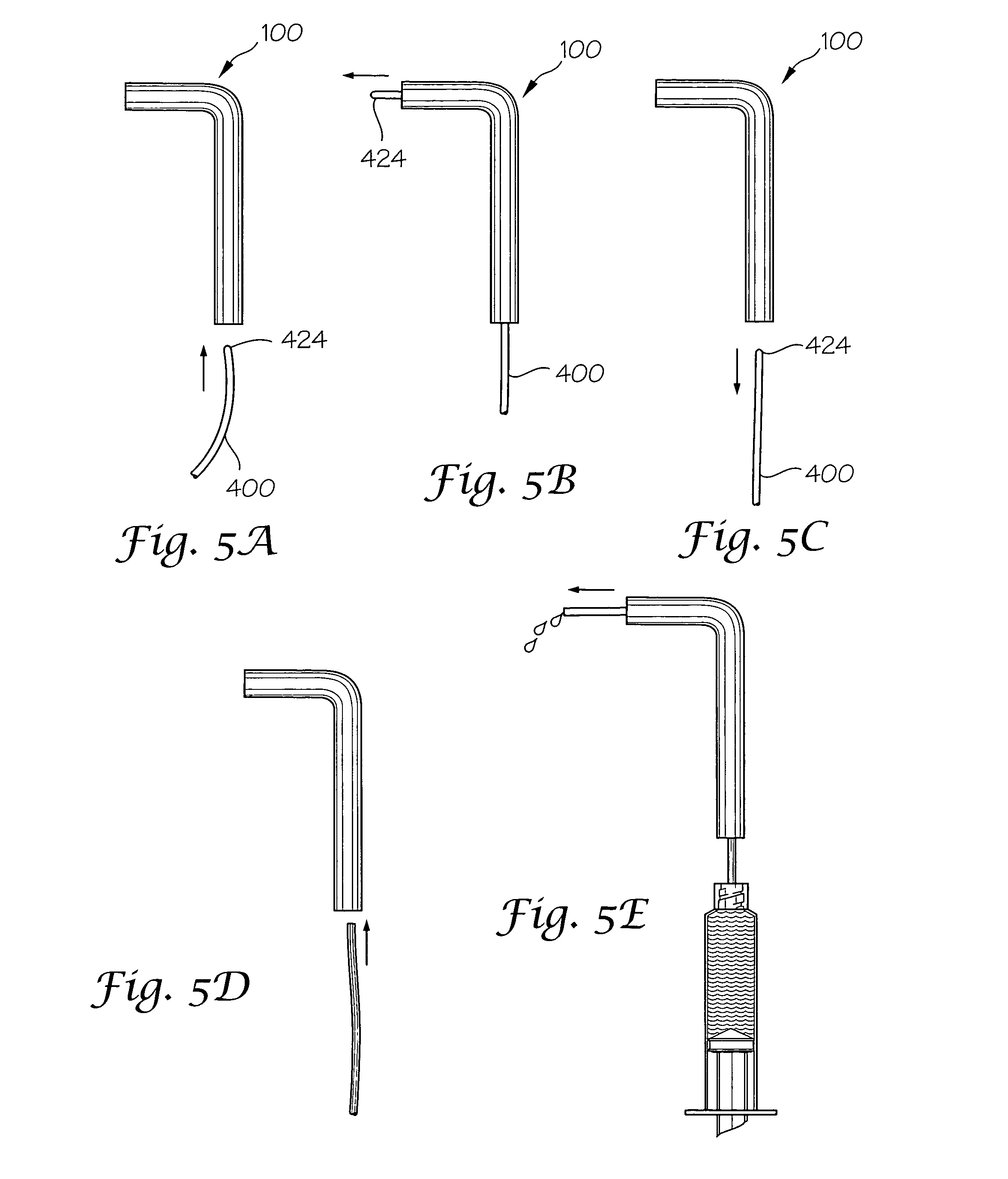
[0041] 2) The right angle guide conduit is inserted with the distal end of the conduit pointing cephalad in the dorsal midline.

[0042] 3) Initial metal stylet wire with ball tip is inserted to “clear a path” for the injection catheter. This can be advanced a few millimeters to a few centimeters.

[0043] 4) Insertion of the catheter with guide wire through the conduit with the distal tip threaded 3 to 5 inches above the surgical site (to the anatomic bony level of L1 to T10). Note that the surgical site may be at any appropriate loc...


PUM


Abstract

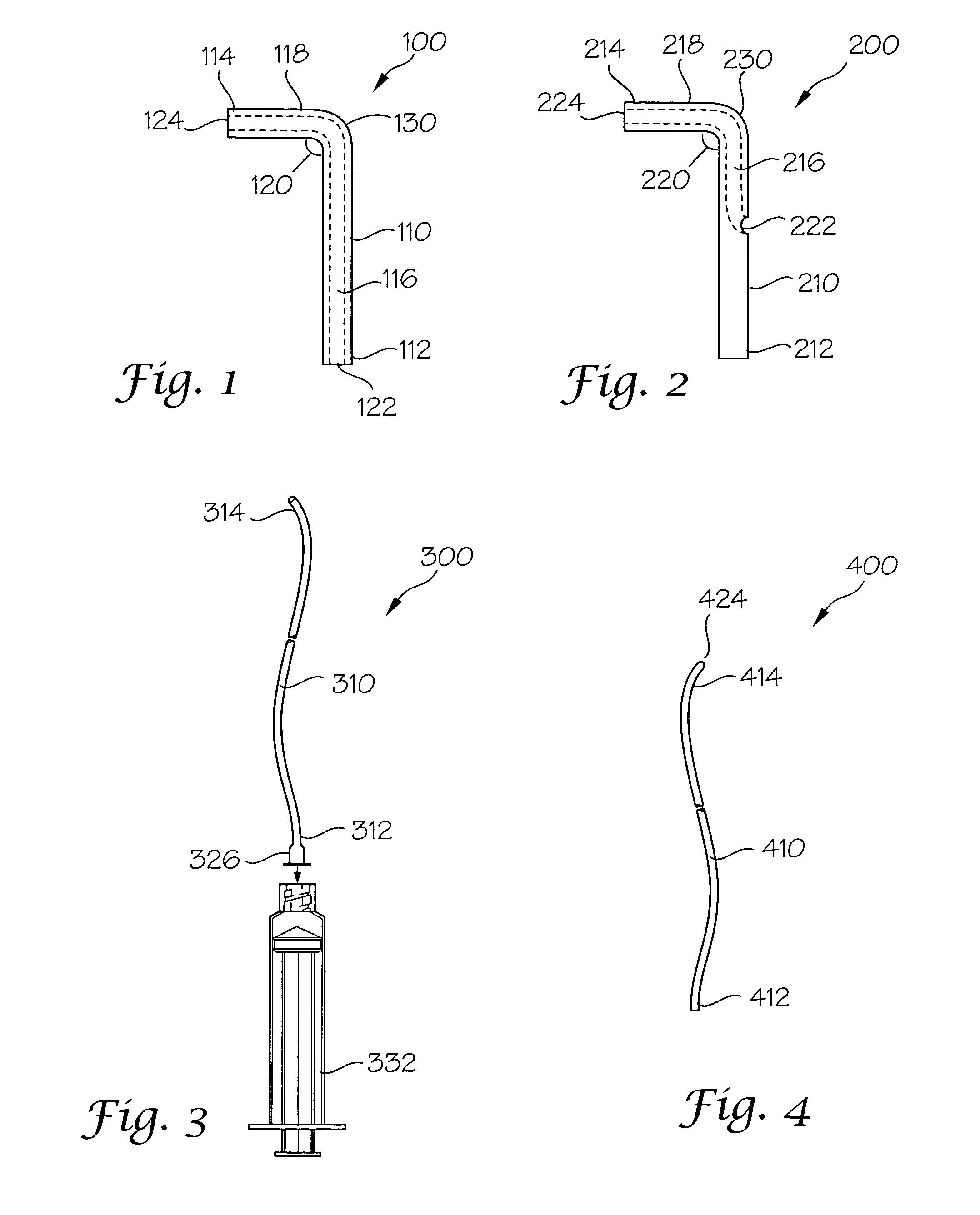
Disclosed herein is a catheter placement apparatus 900 for assisting in the placement of a catheter for administering analgesia intraoperatively in conjunction with spinal and other surgeries. The catheter placement apparatus 900 comprises a guide conduit 903 having a proximal end 904 and a distal end 906. The guide conduit 903 comprises an elongated portion 905 and a delivery arm portion 907 with a bend 935 forming the transition from the elongated portion 905 to the delivery arm portion 907. The elongated portion comprises a first conduit component 910 that is slidingly attachable to a second conduit component 915.

Description

BACKGROUND OF THE INVENTION [0001] When patients emerge from general anesthesia after a lumbar spinal procedure they often go into lumbar muscle spasms as a result of the incisional pain combined with the abrupt loss of effective lumbar analgesia. This combination often leads to the creation of a pain spasm cycle of the lumbar muscles at the incisional wound area where the local muscle spasms cause more incisional area pain, which then cause more local muscle spasms and even more pain. Often intravenous narcotics and benzodiazepines are required to break this cycle which can last from thirty minutes to hours and in severe cases even days. This pain spasm cycle is not only quite uncomfortable to the patient but additionally prevent many patients with a smaller procedure such as a discectomy or laminoforaminotomy (typically the L4-L5 or L5-S1 level and occasionally the L3-L4 level) from going home on the day of surgery. Although, the true cost of a patient staying an extra day varies ...

Claims


Application Information

Patent Timeline
IPC IPC(8): A61M31/00
CPCA61M25/0113
Inventor GEISLER, FRED H.BECKER, DANIEL L.
Owner SPINAL INTEGRATION
Learn More