Al technical title is built by PatSnap Al team. It summarizes the technical point description of the patent document.
a multi-contact adaptive and fastener technology, applied in the field of fastener clips, can solve the problems of wear and/or noise generation, insufficient accommodation, and the typical lack of noise generation of conventional fastener devices,
Inactive Publication Date: 2006-08-03
MED ENG SYST INC +1
View PDF6 Cites 50 Cited by
Summary
Abstract
Description
Claims
Application Information
AI Technical Summary
This helps you quickly interpret patents by identifying the three key elements:
Problems solved by technology
Method used
Benefits of technology
Problems solved by technology
However, these conventional fastener devices instead provide approximately relatively equal levels of insertion and extraction force.
Further, once the body panel is attached to the chassis via the fastener device, the fastener device is typically required to secure the panel to the chassis under a variety of environmental conditions, such as in the presence of vibration at various levels of amplitude and frequency.
Conventional fastener devices typically do not adequately minimize or eliminate buzzing and rattling and do not sufficiently accommodate variations in production tolerances.
Further, each step has a relatively large rise and run so that, once inserted, movement of the fastener clip within the range of a step size may occur, resulting in wear and/or the generation of noise, including buzzing and rattling as a result of vibrations occurring within the vehicle.
If the tolerances in production of the slot in...
Method used
Image
Click on the blue label to locate the original text in one second.
Reading with bidirectional positioning of images and text.
Examples
Embodiment Construction
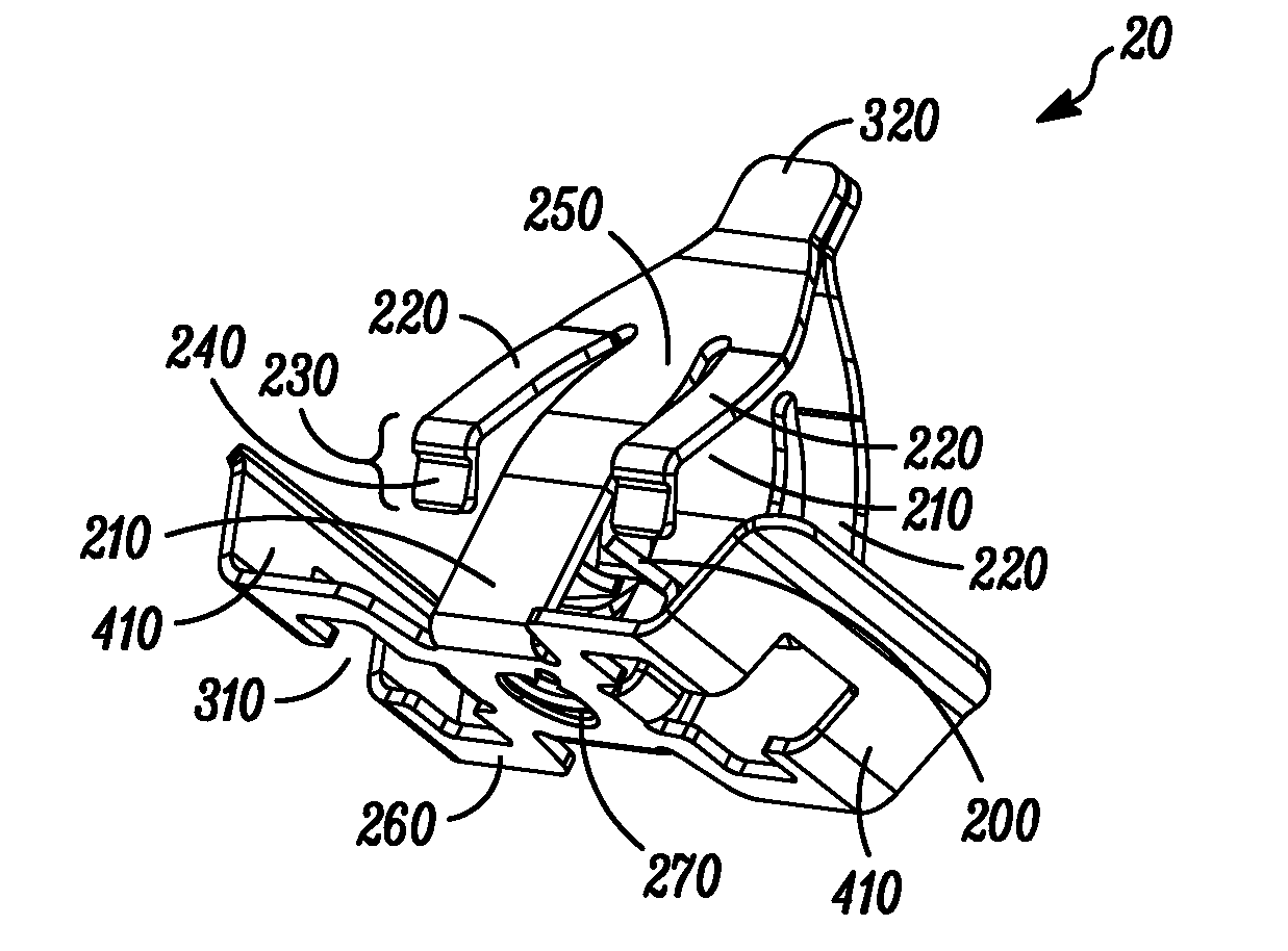
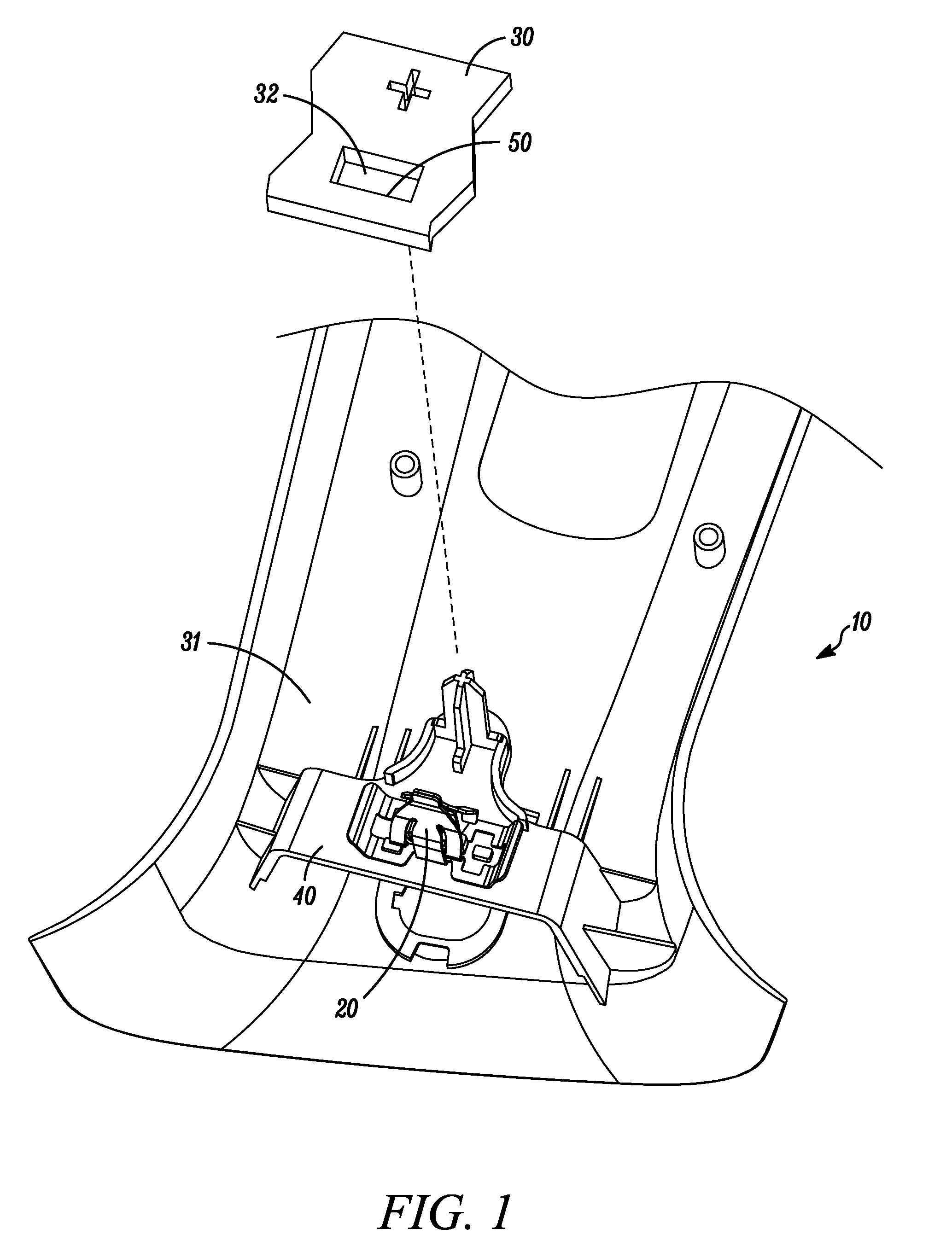
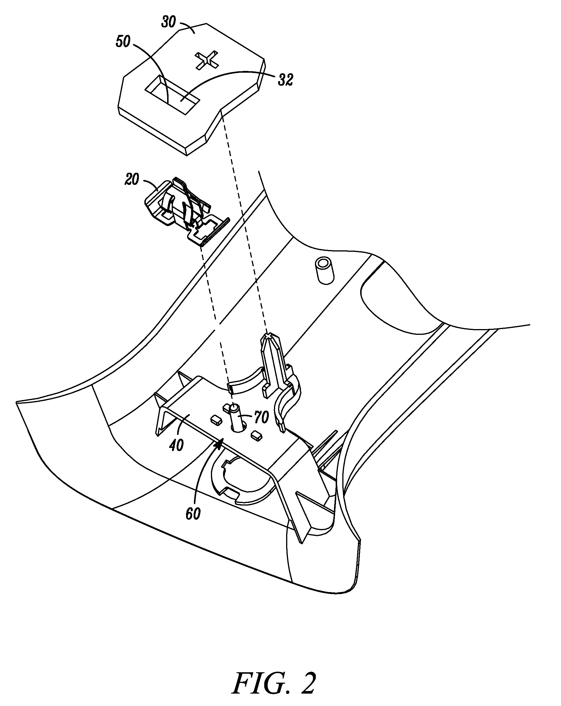
[0026] A fastener clip includes a base plate and a pair of laterally offset arms extending from the base plate. The fastener clip is operative for insertion into a hole (slot) defined in a first engagement structure, such as a vehicle chassis. At least four wings extend from the arms. Each wing includes at least one engagement portion, including a depressed portion formed on each wing, wherein each depressed portion is operative to engage a portion of the hole. According to one embodiment, each arm is coupled to at least one wing at a distal end of each arm (i.e., a long arm), so that each wing extends inwardly towards the base plate. According to an alternative embodiment, each arm (i.e., a short arm) is coupled to the at least one wing, so that each wing extends outwardly away from the base plate.
[0027] Among other advantages, the fastener clip relatively easily facilitates attachment of a body panel, such as an interior or exterior body panel with the first engagement structure,...
PUM
Abstract
A fastener clip includes a base plate and a pair of laterally offset arms extending from the base plate. The fastener clip is operative for insertion into a hole (slot) defined in a first engagement structure, such as a vehicle chassis. At least four wings extend from the arms. Each wing includes at least one engagement portion including a depressed portion formed on each wing, wherein each depressed portion is operative to engage a portion of the hole. According to one embodiment, each arm is coupled to at least one wing at a distal end of each arm (i.e., a long arm), so that each wing extends inwardly towards the base plate. According to an alternative embodiment, each arm (i.e., a short arm) is coupled to the at least one wing, so that each wing extends outwardly away from the base plate.
Description
RELATED APPLICATIONS [0001] This application is a continuation in part claiming priority from an application entitled “Vehicles Comprising Assemblies Having Fastener with Ergonomically Balanced Removal to Insertion Force Ratio” having a docket number of TE9D2 and U.S. patent application Ser. No. 10 / 704,094, which is a divisional Application of non-provisional application Ser. No. 10 / 164,963 with a docket number of TE9, filed Jun. 7, 2002, now U.S. Pat. No. 6,718,599, which claims priority to provisional applications 60 / 301,364, filed Jun. 25, 2001, 60 / 327,814, filed Oct. 9, 2001, and 60 / 353,515 filed Feb. 1, 2002, all of which are incorporated herein by reference in their entirety. [0002] This application is a continuation in part of U.S. patent application Ser. No. 10 / 906,209 having a docket number 04.001 filed on Feb. 9, 2005, the entire disclosure of which is incorporated herein by reference.FIELD OF THE INVENTIONS [0003] The invention relates generally to devices for fastening o...
Claims
Application Information
Patent Timeline
Application Date:The date an application was filed.
Publication Date:The date a patent or application was officially published.
First Publication Date:The earliest publication date of a patent with the same application number.
Issue Date:Publication date of the patent grant document.
PCT Entry Date:The Entry date of PCT National Phase.
Estimated Expiry Date:The statutory expiry date of a patent right according to the Patent Law, and it is the longest term of protection that the patent right can achieve without the termination of the patent right due to other reasons(Term extension factor has been taken into account ).
Invalid Date:Actual expiry date is based on effective date or publication date of legal transaction data of invalid patent.