L-beam piezoresistance type micro-accelerometer and production method thereof

An accelerometer and L-shaped beam technology, applied in the field of micro-electronic mechanical systems, can solve the problems of small cross-interference, high sensitivity, low cost, etc., and achieve the effects of suppressing cross-interference, high sensitivity, and easy implementation

Inactive Publication Date: 2008-09-24
SHANGHAI INST OF MICROSYSTEM & INFORMATION TECH CHINESE ACAD OF SCI
View PDF0 Cites 16 Cited by
  • Summary
  • Abstract
  • Description
  • Claims
  • Application Information

AI Technical Summary

Problems solved by technology

[0005] The present invention proposes a piezoresistive micro-accelerometer with an L-shaped beam and a manufacturing method thereof in order to solve the shortcomings of existing piezoresistive micro-accelerometers that cannot simultaneously satisfy the shortcomings of high sensitivity, small size, low cost, small cross-interference, and easy processing. The L-beam piezoresistive micro-accelerometer is shown in Figure 2-1

Method used


Image

  • L-beam piezoresistance type micro-accelerometer and production method thereof
  • L-beam piezoresistance type micro-accelerometer and production method thereof
  • L-beam piezoresistance type micro-accelerometer and production method thereof

Examples


Embodiment 1

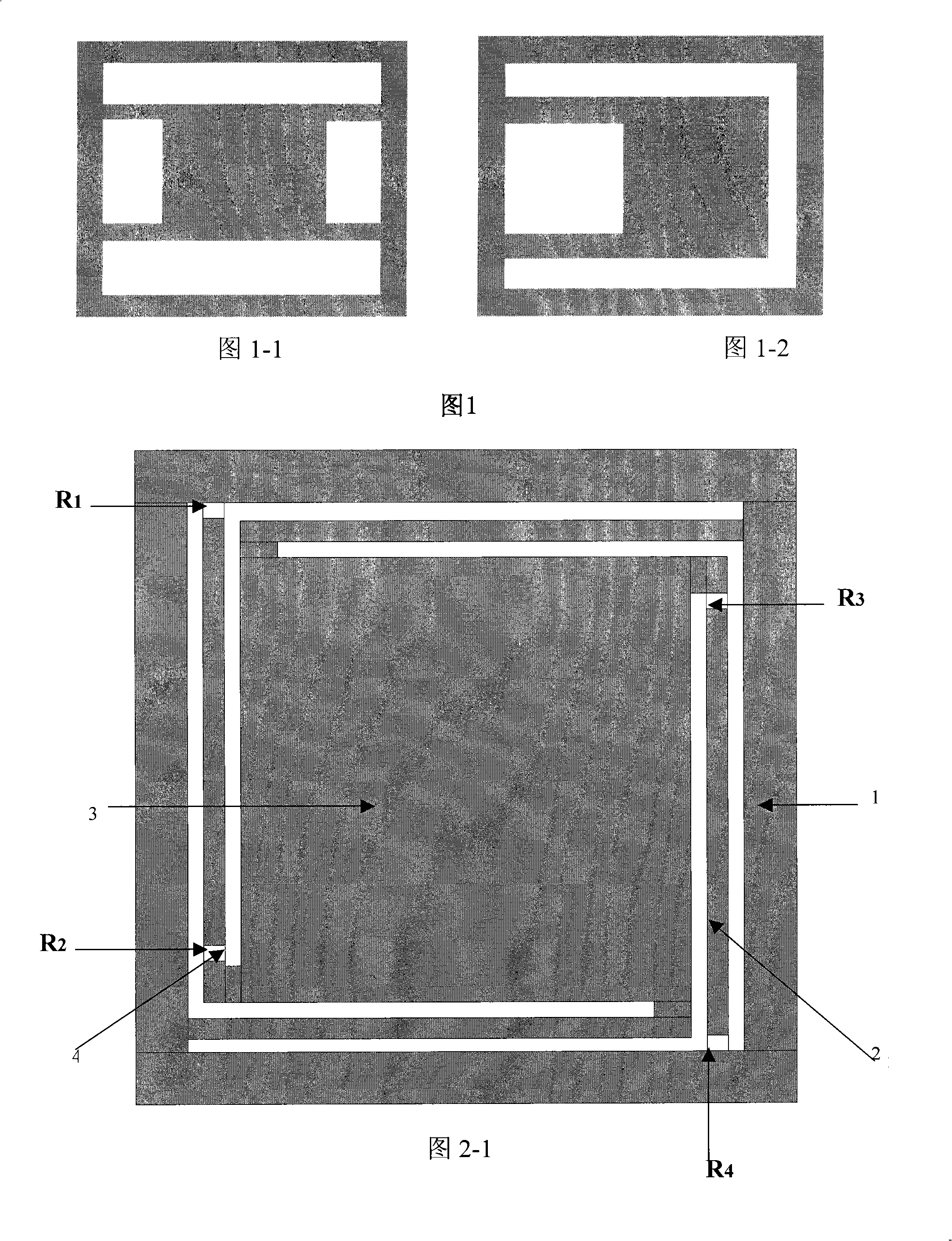
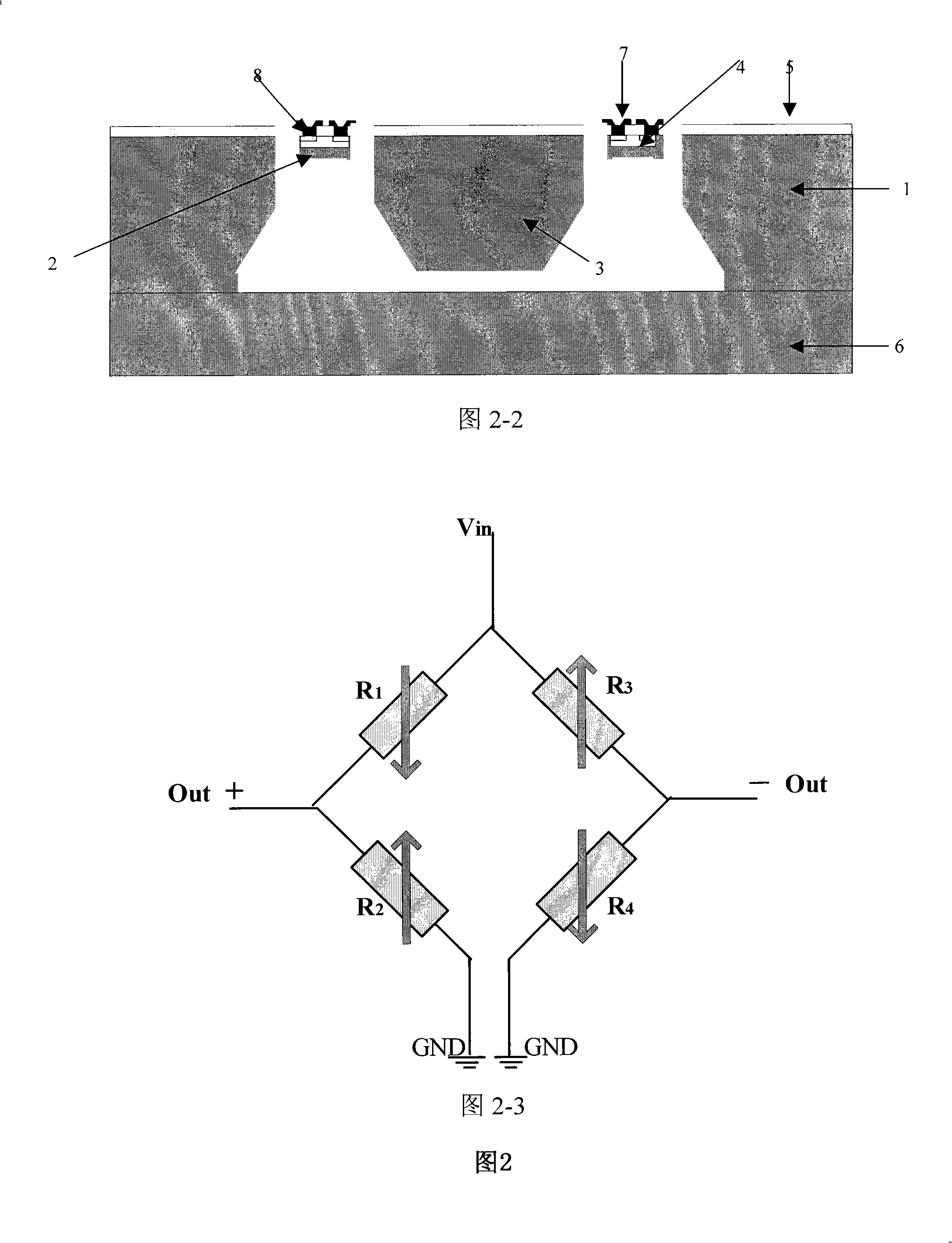
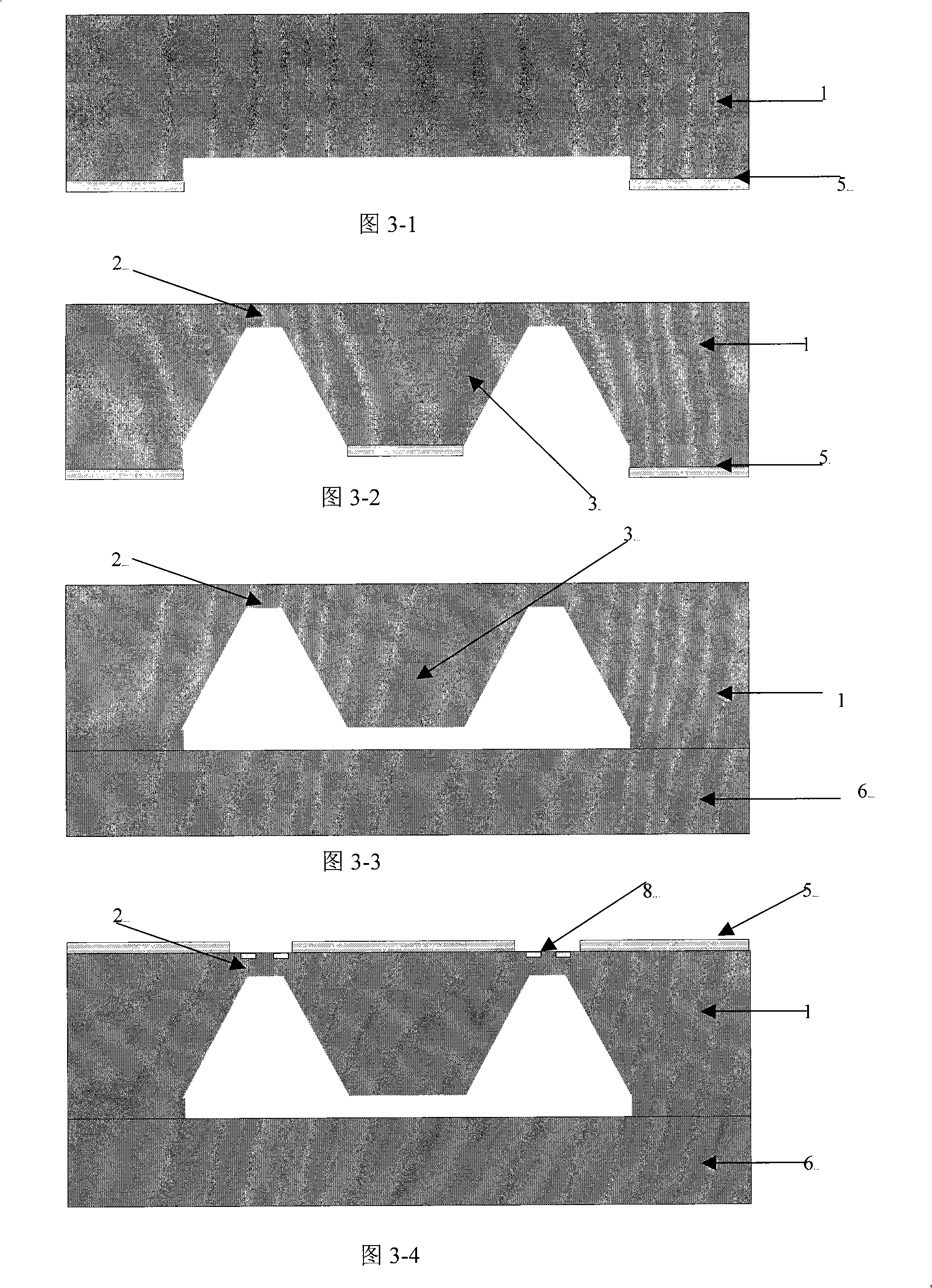
[0033] (1) On the polished silicon wafer 1, first thermally grow the silicon dioxide layer 5, perform front photolithography, and make alignment marks, perform damping gap photolithography on the back side of the silicon wafer, and etch the damping gap by wet etching . See Figure 3-1.

[0034] (2) On the silicon wafer on which the damping gap is formed in step 1, a layer of silicon dioxide is first formed by a thermal oxidation method, photolithography of the mass block 3 is performed, and the mass block structure is etched out with KOH. See Figure 3-2

[0035] (3) Removing the silicon dioxide layer on the mass silicon wafer etched out in step 2, and performing silicon-silicon bonding with another polished silicon wafer as the lower cover plate 6 . See Figure 3-3.

[0036] (4) The silicon wafer after the silicon-silicon bonding in step 3 is oxidized to grow an oxide layer, and the contact hole window 8 is photoetched to implant high-concentration boron ions. See Figure 3-4...

Embodiment 2

[0044] The specific implementation steps are the same as those in Example 1, the main difference is that in Example 1, when the beam window is photolithographically etched in step 9, only one L-shaped elastic beam is etched at the two opposite corners of the mass block, instead of In Embodiment 1, the beam windows are etched at the four corners of the proof mass, and the rest of the steps are the same as those in Embodiment 1. The top view of the structure of the piezoresistive micro-accelerometer constructed in this embodiment is shown in Figure 4-1.

Embodiment 3

[0046] The specific implementation steps are the same as those in Example 1, the main difference being that when the beam window is photolithographically etched in Step 9 of Example 1, only one L-shaped elastic beam is etched at the two corners of the same side of the mass block, Instead of etching beam windows at the four corners of the mass block in Example 1, the rest of the steps are the same as those in Example 1. The top view of the piezoresistive micro-accelerometer structure constructed in this example is shown in Fig. 4-2 shown.


PUM


Abstract

The invention relates to an L-beam piezoresistance type micro-accelerometer and a production method thereof, the micro-accelerometer comprises a supporting main framework body, an elastic beam, a weight block, cover plates and so on, which is characterized in that the elastic beam is shaped like L, a long arm of the L-shaped elastic beam is connected with a side frame of the supporting main framework body, the weight block is suspended in the middle of a supporting side frame body by the support of the L-shaped elastic beam, a short arm of the L-shaped elastic beam is connected with the top angle of the upper surface of the weight block; the upper and the lower surfaces of the supporting main framework body are bonded with the cover plates; the root part and the top end of the long arm of the L-shaped beam are respectively provided with a piezoresistor, and the two piezoresistors with the same resistance on the L-shaped beam constitute a bridge with the unilateral strain of a Wheatstone bridge. The micro-electron mechanical processing technology is adopted as the key production technology. The L-beam piezoresistance type micro-accelerometer can solve the problem that the existing piezoresistance type micro-accelerometer can not simultaneously meet the requirements of high sensitivity, small volume, low cost, small cross-interference and easy processing.

Description

technical field [0001] The invention relates to a piezoresistive micro accelerometer and a manufacturing method thereof, more precisely to a piezoresistive micro accelerometer with an L-shaped elastic beam and a manufacturing method thereof. It belongs to the technical field of microelectromechanical systems (MEMS). Background technique [0002] As an inertial device, the accelerometer has a wide range of applications in vibration and shock measurement in the fields of automobiles, electronics, and machinery, navigation for ships, aircraft, and spacecraft, and vibration testing for oil exploration and earthquake prediction. Micro-accelerometers produced by Micro-machining-Technology have the advantages of low cost, small size, light weight, high stability, and mass production, so they have broad military and civilian prospects. The current micro accelerometers are mainly classified according to the detection methods: capacitive type, piezoresistive type, piezoelectric type,...

Claims


Application Information

Patent Timeline
Patent Type & Authority Applications(China)
IPC IPC(8): G01P15/12B81B7/02B81C1/00
Inventor 熊斌高廷金车录锋王跃林
Owner SHANGHAI INST OF MICROSYSTEM & INFORMATION TECH CHINESE ACAD OF SCI
Why Eureka
Try Eureka