

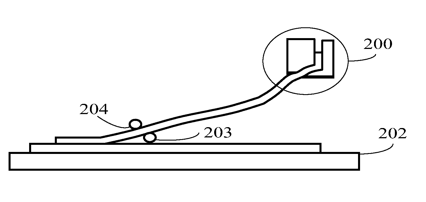
Method of fully, automatically removing a polarizer of an LCD panel
a technology of lcd panel and polarizer, which is applied in the field of automatic removal of lcd panel polarizers, can solve the problems of high risk of damage or scratching of polarizers, long time-consuming and labor-intensive removal, and inability to fully manual remove polarizers, so as to reduce the risk of work-related injuries, reduce the ratio of successfully removing polarizers, and improve the efficiency of removing polarizers
- Summary
- Abstract
- Description
- Claims
- Application Information
AI Technical Summary
Benefits of technology
Problems solved by technology
Method used
Image

Examples
Embodiment Construction
[0027]Various embodiments of the disclosure are now described in detail. Referring to the drawings, like numbers indicate like parts throughout the views. As used in the description herein and throughout the claims that follow, the meaning of “a,”“an,” and “the” includes plural reference unless the context clearly dictates otherwise. Also, as used in the description herein and throughout the claims that follow, the meaning of “in” includes “in” and “on” unless the context clearly dictates otherwise.
[0028]In order to further describe the technical solutions adopted to achieve the objectives of the present disclosure and the efficacies thereof, implementations, methods, steps, structures, features and efficacies of the color flat display panel and the corresponding color flat display device according to the present disclosure will be detailed hereinbelow with reference to the attached drawings and preferred embodiments thereof. The aforesaid and other technical disclosures, features a...
PUM
| Property | Measurement | Unit |
|---|---|---|
| charge- | aaaaa | aaaaa |
| image processing | aaaaa | aaaaa |
| speed | aaaaa | aaaaa |
Abstract
Description
Claims
Application Information