Air-conditioning thermostat

Inactive Publication Date: 2006-08-03
FRY WARREN C
View PDF15 Cites 19 Cited by
  • Summary
  • Abstract
  • Description
  • Claims
  • Application Information

AI Technical Summary

Benefits of technology

[0036] (m) to reduce or eliminate

Problems solved by technology

Under low heat-load traditional thermostats have temperature undershoot which results in exc

Method used


Image

  • Air-conditioning thermostat
  • Air-conditioning thermostat
  • Air-conditioning thermostat

Examples


Example

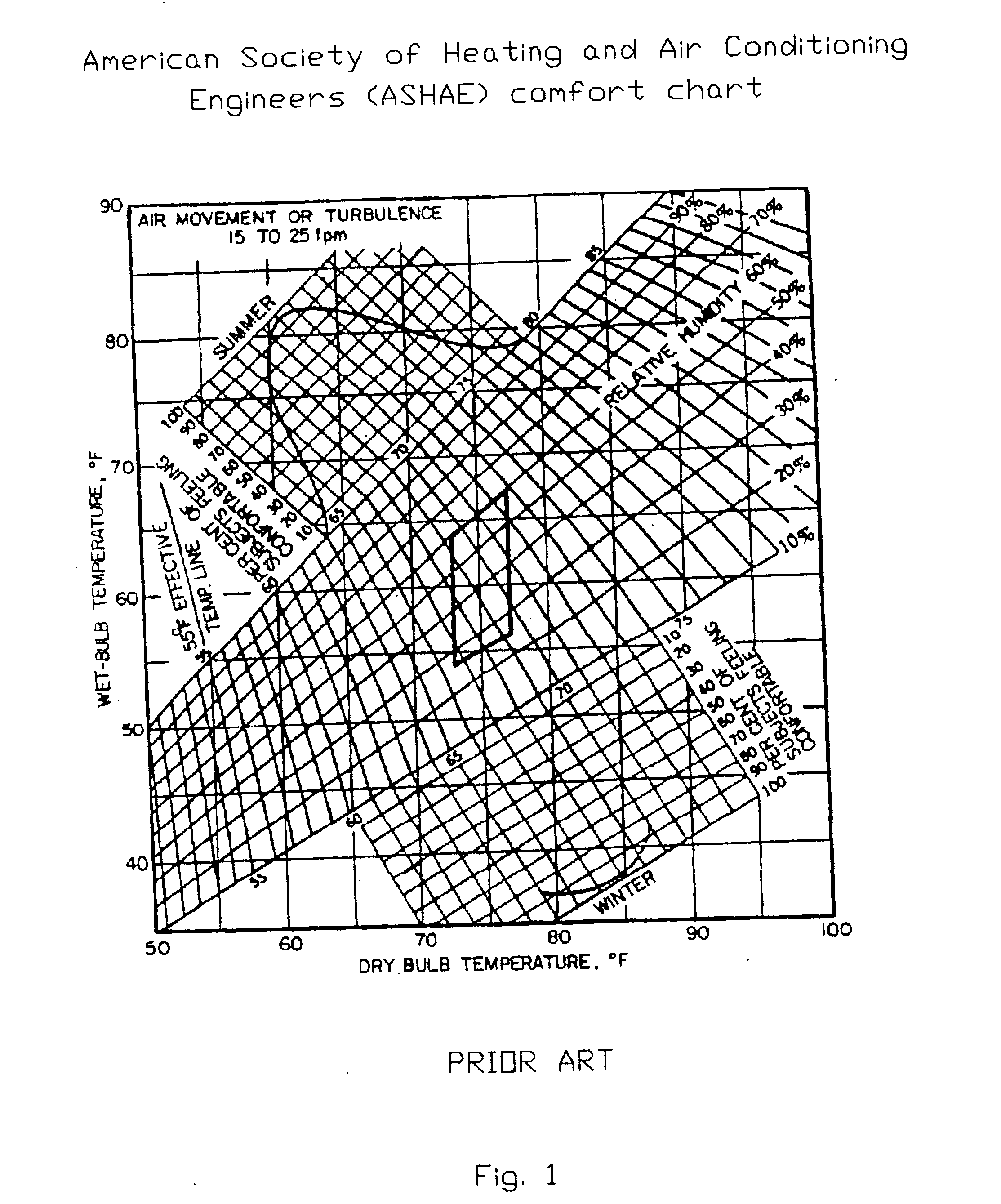
[0049]FIG. 1 ASHAE comfort chart shows the relationship of temperature and relative humidity, as it effects comfort summer and winter.

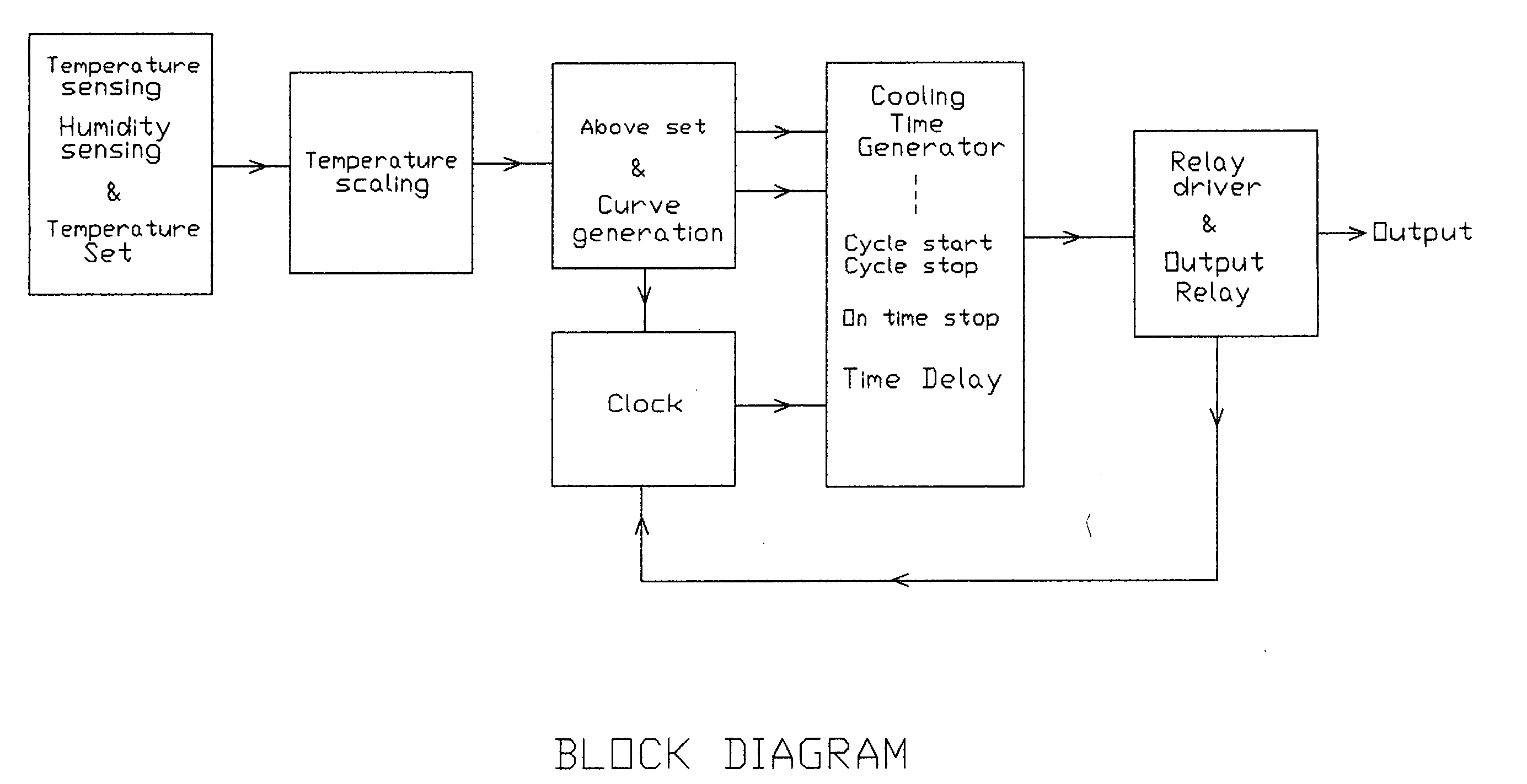
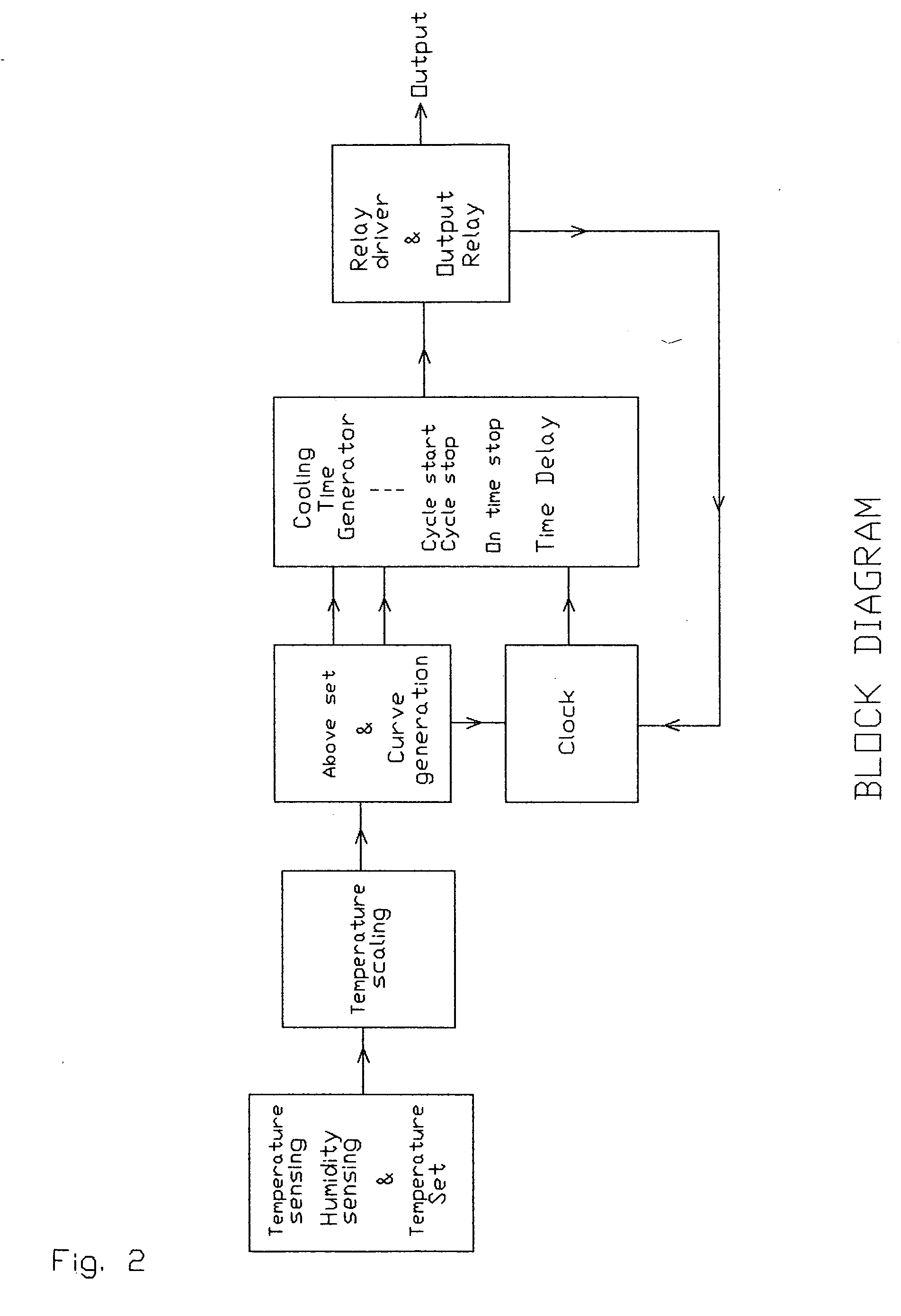
[0050]FIG. 2 shows a block diagram of my thermostat. The sensed temperature, humidity and temperature-set are combined to permit a user to select desired minimum effective temperature. The difference between indoor effective temperature and temperature-set is sent to temperature scaling, where the user selects an acceptable cooling response to temperature above temperature set. The scaled signal is sent to a curve generation block where the signal is split. One path is scaled linear or non-linear. And a second path determines if temperature is above or below temperature-set. These two signals are sent to the cooling time generator block and to the clock block. The clock block signal is also sent to the Cooling time generator block. In this block the signals are processed by the Cycle start, Cycle stop, On time stop and Time delay to generate an outpu...


PUM


Abstract

A thermostat based on indoor effective-temperature with cooling time a function of the difference between the inside temperature and temperature-set while off time is the remainder of a time cycle. This permits indoor temperature to vary with heat-load to provide comfort and conserve power under all heat-load conditions. During high heat-load conditions it can provide comfort and save a significant amount of power. It provides comfort down to temperature-set, when the heat load decreases in the evenings and at night. For low heat-load conditions, it eliminates cooling under-shoot and controlled off time reduces or eliminates stuffiness between cooling cycles.

Description

CROSS-REFERENCE TO RELATED APPLICATIONS [0001] Not Applicable FEDERALLY SPONSORED RESEARCH [0002] Not Applicable SEQUENCE LISTING OR PROGRAM [0003] Not Applicable BACKGROUND OF THE INVENTION [0004] 1. Field of Invention [0005] This invention relates to air conditioning thermostats that use a relative humidity sensor to modify the sensed temperature and permit the inside temperature to change as a function of the heat-load imposed on the air conditioning system. [0006] 2. Background of the Invention [0007] The control method used in most conventional air-conditioning thermostats operates on an absolute temperature control principal. The desired indoor temperature is set by the temperature control irrespective of variation in outdoor temperature. Excessive cooling or inadequate cooling of a house or room adversely effects the physical condition of some or all of occupants in a house or room. Electrical power is wasted when an air conditioner provides cooling in excess of the amount re...

Claims


Application Information

Patent Timeline
IPC IPC(8): F24F7/00G05D23/32F28D1/00F28F13/00
CPCF24F11/0012F24F11/0015F24F11/30F24F2110/10F24F2110/20F24F11/64F24F11/61F24F11/88F24F11/46
Inventor FRY, WARREN C.
Owner FRY WARREN C
Why Eureka
Try Eureka